Serial programming pin mapping, Atmega169v/l – Rainbow Electronics Atmega169L User Manual
Page 270
270
ATmega169V/L
2514A–AVR–08/02
Serial Programming Pin
Mapping
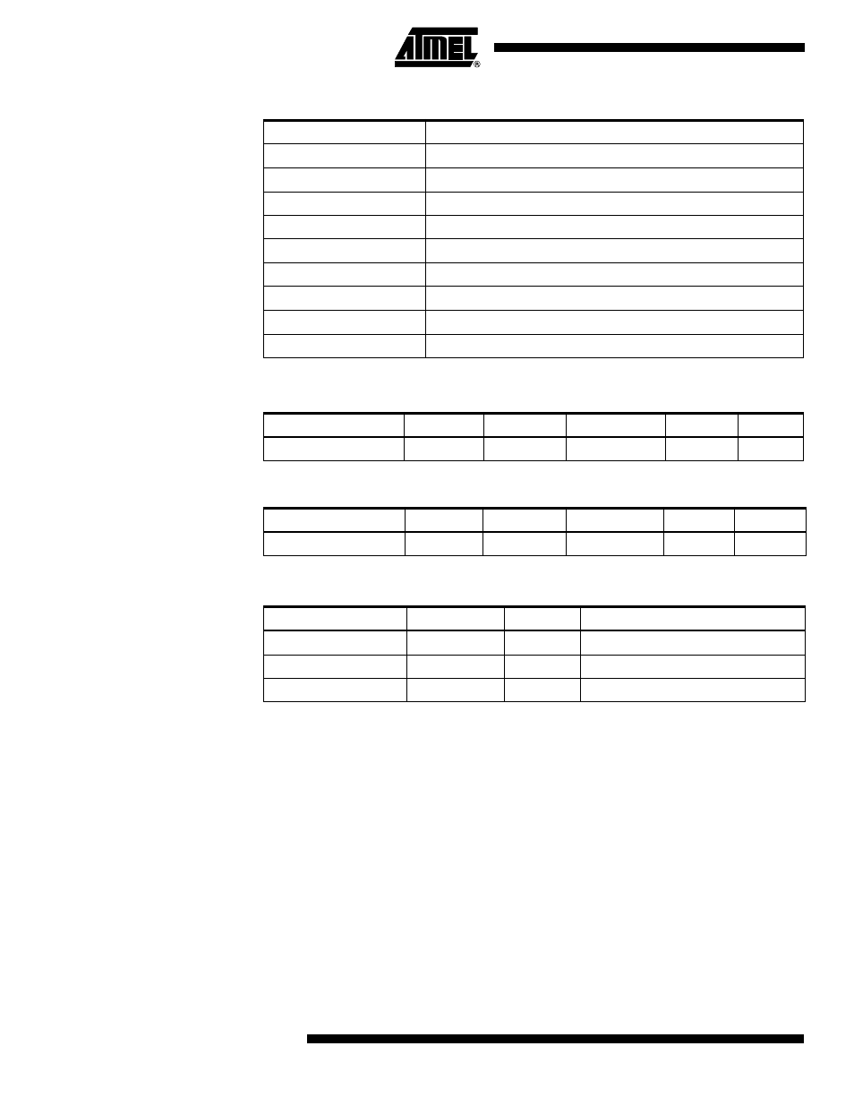
Table 124. Command Byte Bit Coding
Command Byte
Command Executed
1000 0000
Chip Erase
0100 0000
Write Fuse bits
0010 0000
Write Lock bits
0001 0000
Write Flash
0001 0001
Write EEPROM
0000 1000
Read Signature Bytes and Calibration byte
0000 0100
Read Fuse and Lock bits
0000 0010
Read Flash
0000 0011
Read EEPROM
Table 125. No. of Words in a Page and No. of Pages in the Flash
Flash Size
Page Size
PCWORD
No. of Pages
PCPAGE
PCMSB
8K words (16K bytes)
64 words
PC[5:0]
128
PC[12:6]
12
Table 126. No. of Words in a Page and No. of Pages in the EEPROM
EEPROM Size
Page Size
PCWORD
No. of Pages
PCPAGE
EEAMSB
512 bytes
4 bytes
EEA[1:0]
128
EEA[8:2]
8
Table 127. Pin Mapping Serial Programming
Symbol
Pins
I/O
Description
MOSI
PB2
I
Serial Data in
MISO
PB3
O
Serial Data out
SCK
PB1
I
Serial Clock
- MAX5151 (16 pages)
- MAXQ3108 (64 pages)
- MAX5661 (39 pages)
- MAX6691 (7 pages)
- MAX5362 (12 pages)
- ADC10158 (26 pages)
- MAX8922L (14 pages)
- MAX8596Z (8 pages)
- MAX7491 (18 pages)
- MAX15040 (15 pages)
- MAX5177 (16 pages)
- ADC08138 (22 pages)
- MAX5961 (42 pages)
- T89C51RD2 (86 pages)
- MAX16055 (9 pages)
- MAX6659 (17 pages)
- ADC0820 (20 pages)
- MAX6678 (19 pages)
- MAX8884Z (15 pages)
- MAX16915 (9 pages)
- MAX8620 (18 pages)
- MAX5144 (12 pages)
- MAX6670 (8 pages)
- MAX8760 (39 pages)
- W78C32C (14 pages)
- MX7533 (8 pages)
- MAX8727 (13 pages)
- MAX9053 (15 pages)
- W78C54 (16 pages)
- MAX8614B (15 pages)
- W90N740 (219 pages)
- MAX6626 (13 pages)
- ADC10738 (30 pages)
- MAX17000 (31 pages)
- MAX5051 (21 pages)
- MAXQ1004 (18 pages)
- MAX6871 (51 pages)
- MX7847 (12 pages)
- MAX6608 (6 pages)
- MAX17083 (15 pages)
- MAX6641 (17 pages)
- MAX5251 (16 pages)
- MAX6338 (8 pages)
- MAX6690 (16 pages)
- MAX8668 (18 pages)