Lcd frame rate register – lcdfrr, Atmega169v/l – Rainbow Electronics Atmega169L User Manual
Page 221
221
ATmega169V/L
2514A–AVR–08/02
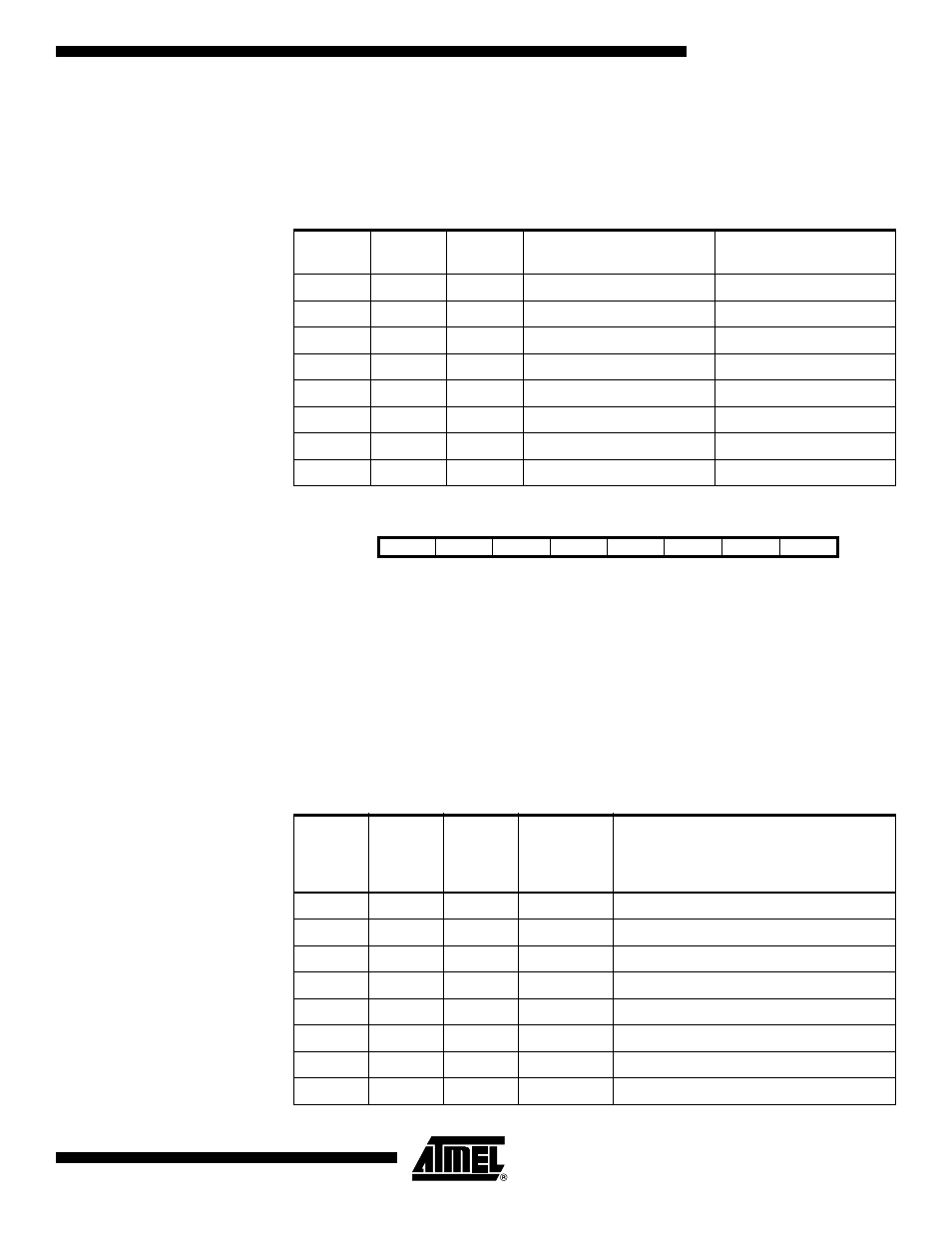
• Bits 2:0 – LCDPM2:0: LCD Port Mask
The LCDPM2:0 bits determine the number of port pins to be used as segment drivers.
The different selections are shown in Table 95. Unused pins can be used as ordinary
port pins.
LCD Frame Rate Register –
LCDFRR
• Bit 7 – Res: Reserved Bit
This bit is reserved bit in the ATmega169 and will always read as zero.
• Bits 6:4 – LCDPS2:0: LCD Prescaler Select
The LCDPS2:0 bits selects tap point from a prescaler. The prescaled output can be fur-
ther divided by setting the clock divide bits (LCDCD2:0). The different selections are
shown in Table 96. Together they determine the prescaled LCD clock (clk
LCD_PS
), which
is clocking the LCD module.
Table 95. LCD Port Mask
LCDPM2
LCDPM1
LCDPM0
I/O Port in Use as
Segment Driver
Maximum Number of
Segments
0
0
0
SEG0:12
13
0
0
1
SEG0:14
15
0
1
0
SEG0:16
17
0
1
1
SEG0:18
19
1
0
0
SEG0:20
21
1
0
1
SEG0:22
23
1
1
0
SEG0:23
24
1
1
1
SEG0:24
25
Bit
7
6
5
4
3
2
1
0
–
LCDPS2
LCDPS1
LCDPS0
–
LCDCD2
LCDCD1
LCDCD0
LCDFRR
Read/Write
R
R/W
R/W
R/W
R
R/W
R/W
R/W
Initial Value
0
0
0
0
0
0
0
0
Table 96. LCD Prescaler Select
LCDPS2
LCDPS1
LCDPS0
Output
from
Prescaler
clk
LCD
/N
Applied Prescaled LCD Clock
Frequency when LCDCD2:0 = 0,
Duty = 1/4, and Frame Rate = 64 Hz
0
0
0
clk
LCD
/16
8.1 kHz
0
0
1
clk
LCD
/64
33 kHz
0
1
0
clk
LCD
/128
66 kHz
0
1
1
clk
LCD
/256
130 kHz
1
0
0
clk
LCD
/512
260 kHz
1
0
1
clk
LCD
/1024
520 kHz
1
1
0
clk
LCD
/2048
1 MHz
1
1
1
clk
LCD
/4096
2 MHz