Atmega169v/l – Rainbow Electronics Atmega169L User Manual
Page 205
205
ATmega169V/L
2514A–AVR–08/02
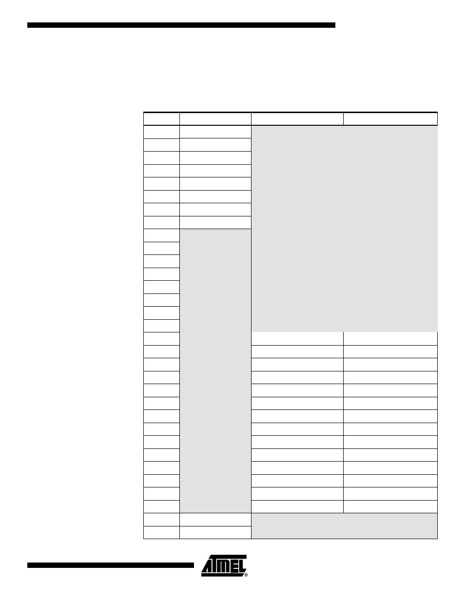
• Bits 4:0 – MUX4:0: Analog Channel Selection Bits
The value of these bits selects which combination of analog inputs are connected to the
ADC. See Table 90 for details. If these bits are changed during a conversion, the
change will not go in effect until this conversion is complete (ADIF in ADCSRA is set).
Table 90. Input Channel Selections
MUX4..0
Single Ended Input
Positive Differential Input
Negative Differential Input
00000
ADC0
N/A
00001
ADC1
00010
ADC2
00011
ADC3
00100
ADC4
00101
ADC5
00110
ADC6
00111
ADC7
01000
01001
01010
01011
01100
01101
01110
01111
10000
ADC0
ADC1
10001
ADC1
ADC1
10010
N/A
ADC2
ADC1
10011
ADC3
ADC1
10100
ADC4
ADC1
10101
ADC5
ADC1
10110
ADC6
ADC1
10111
ADC7
ADC1
11000
ADC0
ADC2
11001
ADC1
ADC2
11010
ADC2
ADC2
11011
ADC3
ADC2
11100
ADC4
ADC2
11101
ADC5
ADC2
11110
1.1V (V
BG
)
N/A
11111
0V (GND)
- MAX5151 (16 pages)
- MAXQ3108 (64 pages)
- MAX5661 (39 pages)
- MAX6691 (7 pages)
- MAX5362 (12 pages)
- ADC10158 (26 pages)
- MAX8922L (14 pages)
- MAX8596Z (8 pages)
- MAX7491 (18 pages)
- MAX15040 (15 pages)
- MAX5177 (16 pages)
- ADC08138 (22 pages)
- MAX5961 (42 pages)
- T89C51RD2 (86 pages)
- MAX16055 (9 pages)
- MAX6659 (17 pages)
- ADC0820 (20 pages)
- MAX6678 (19 pages)
- MAX8884Z (15 pages)
- MAX16915 (9 pages)
- MAX8620 (18 pages)
- MAX5144 (12 pages)
- MAX6670 (8 pages)
- MAX8760 (39 pages)
- W78C32C (14 pages)
- MX7533 (8 pages)
- MAX8727 (13 pages)
- MAX9053 (15 pages)
- W78C54 (16 pages)
- MAX8614B (15 pages)
- W90N740 (219 pages)
- MAX6626 (13 pages)
- ADC10738 (30 pages)
- MAX17000 (31 pages)
- MAX5051 (21 pages)
- MAXQ1004 (18 pages)
- MAX6871 (51 pages)
- MX7847 (12 pages)
- MAX6608 (6 pages)
- MAX17083 (15 pages)
- MAX6641 (17 pages)
- MAX5251 (16 pages)
- MAX6338 (8 pages)
- MAX6690 (16 pages)
- MAX8668 (18 pages)