Watchdog reset, Mcu status register – mcusr, Atmega169v/l – Rainbow Electronics Atmega169L User Manual
Page 40
40
ATmega169V/L
2514A–AVR–08/02
When the BOD is enabled, and V
CC
decreases to a value below the trigger level (V
BOT-
in Figure 18), the Brown-out Reset is immediately activated. When V
CC
increases above
the trigger level (V
BOT+
in Figure 18), the delay counter starts the MCU after the Time-
out period t
TOUT
has expired.
The BOD circuit will only detect a drop in V
CC
if the voltage stays below the trigger level
for longer than t
BOD
given in Table 16.
Figure 18. Brown-out Reset During Operation
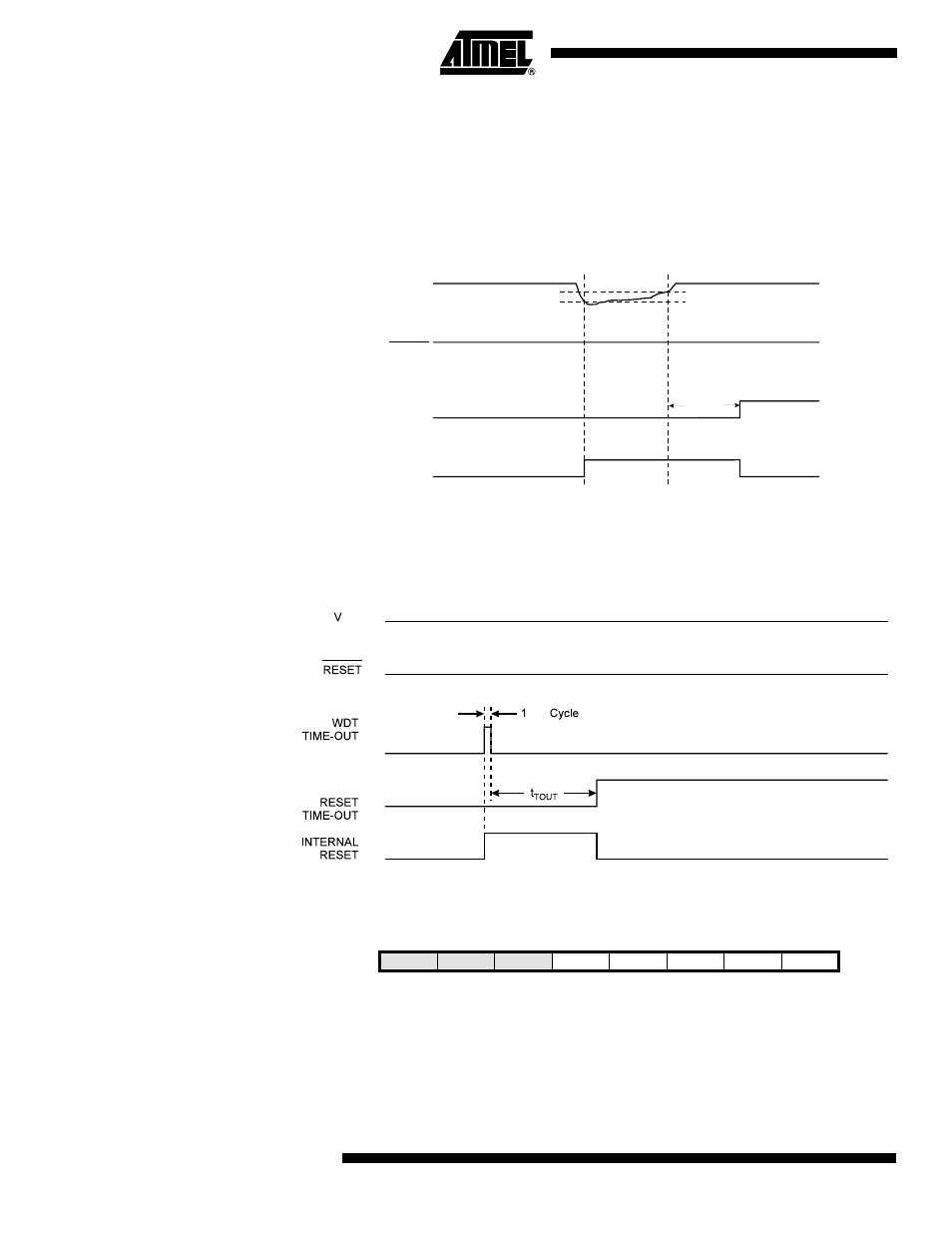
Watchdog Reset
When the Watchdog times out, it will generate a short reset pulse of one CK cycle dura-
tion. On the falling edge of this pulse, the delay timer starts counting the Time-out period
t
TOUT
. Refer to page 42 for details on operation of the Watchdog Timer.
Figure 19. Watchdog Reset During Operation
MCU Status Register –
MCUSR
The MCU Status Register provides information on which reset source caused an MCU
reset.
• Bit 4 – JTRF: JTAG Reset Flag
This bit is set if a reset is being caused by a logic one in the JTAG Reset Register
selected by the JTAG instruction AVR_RESET. This bit is reset by a Power-on Reset, or
by writing a logic zero to the flag.
V
CC
RESET
TIME-OUT
INTERNAL
RESET
V
BOT-
V
BOT+
t
TOUT
CK
CC
Bit
7
6
5
4
3
2
1
0
–
–
–
JTRF
WDRF
BORF
EXTRF
PORF
MCUSR
Read/Write
R
R
R
R/W
R/W
R/W
R/W
R/W
Initial Value
0
0
0
See Bit Description