Pin connections – Xantrex Technology XDC 20-600 User Manual
Page 120
Remote Operation
4–6
TM-XDOP-01XN
Pin Connections
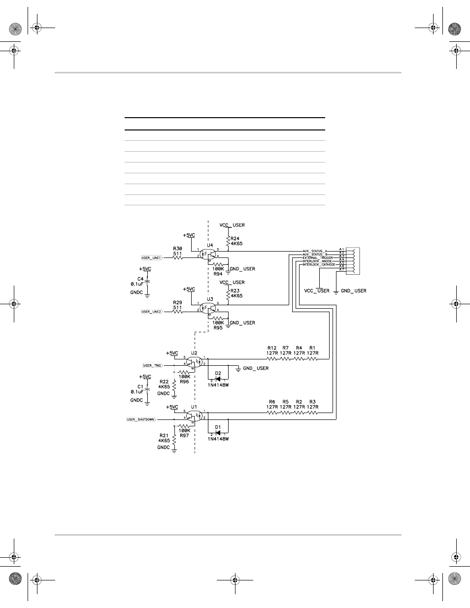
Table 4-1 User Line Pins
Pin #
Function
Input/Output
A1
Aux Status Line A
Output
A2
Aux Status Line B
Output
A3
External Trigger 4–12V
Input
A4
Safety Interlock (Shutdown) 4–12V
Input
A5
Safety Interlock (Shutdown) GND
Input
A6
User Power, 5–12Vdc
Input
A7
User Ground
Input
Figure 4-2 Schematic For User Line Interface
Vf = 1.3V TYP, 1.5V MAX
If = 10mA Recommended, 90mA MAX
CNY17-2
CNY17-2
508 Ohm
0.4W
508 Ohm
0.4W
CNY17-2
CHASSIS POTENTIAL
ISOLATED USER LINES
CNY17-2
USER LINES
TM-XDOP-01XN.book Page 6 Monday, July 17, 2006 11:19 AM
This manual is related to the following products: