Configuration example, Configuration example local management, Remote management – RAD Data comm IPmux-11 User Manual
Page 65
Installation and Operation Manual
Chapter 4 Configuration
IPmux-11 Ver. 2.00
Configuring IPmux-11 for Management
4-7
Configuration Example
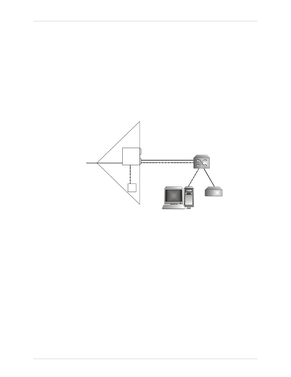
Local Management
illustrates how to manage a local IPmux-11 from an NMS connected via
Ethernet user port 2.
• VLAN tagging mode of the Ethernet user ports is configured to Double Tag
• User and management traffic are separated by different VLANs
• Manager location is set to User2-Eth3.
IPmux-11 separates management traffic sent to the local device MAC and marked
by VLAN 1 from the user traffic marked by VLAN 100. The management traffic is
processed by the local IPmux-11. The user traffic is sent to its destination via the
network interface.
User 2
Network
Management Traffic
(VLAN 1)
User Traffic
(VLAN 100)
VLAN 1
VLAN 100
User 1
Network
Management Station
IPmux-11
User Equipment
Switch
Figure 4-6. Local Management via User Ethernet Port
Remote Management
illustrates how to manage a local and remote IPmux-11 units from an
NMS connected via Ethernet user port 2 of the local device.
• VLAN tagging mode of the Ethernet user ports of both IPmux-11 is configured
to Double Tag
• User and management traffic are separated by different VLANs
• Manager location of the local IPmux-11 is set to User2-Eth3.
• Manager location of the remote IPmux-11 is set to Network-Eth1.
IPmux-11 separates management traffic marked by VLAN 1 from the user traffic
marked by VLAN 100. When the local IPmux-11 detects that the management
traffic has been sent to the MAC of the remote unit, it forwards the traffic to its
destination via the network interface.
The remote IPmux-11 processes the management traffic received via its network
interface and responds to the management requests.