A.2 ethernet connectors, A.3 control connector – RAD Data comm IPmux-11 User Manual
Page 126
Appendix A Connector Wiring
Installation and Operation Manual
A-2 CONTROL
Connector
IPmux-11 Ver. 2.00
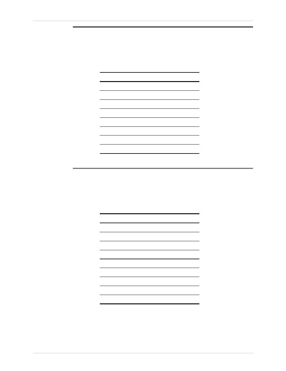
A.2 Ethernet Connectors
The network and user Ethernet electrical interfaces terminate in 8-pin RJ-45
connectors, wired in accordance with
.
Table A-2. Ethernet Connector Pinout
Pin
Function
1 Tx+
2 Tx–
3 Rx+
4 –
5 –
6 Rx–
7 –
8 –
A.3 CONTROL Connector
The control terminal interface terminates in a V.24/RS-232 9-pin D-type female
DCE connector.
lists the CONTROL connector pin assignments.
Table A-3. CONTROL Connector Pinout
Pin
Function
1 –
2 Rx
3 Tx
4 –
5 GND
6 –
7 –
8 –
9 –