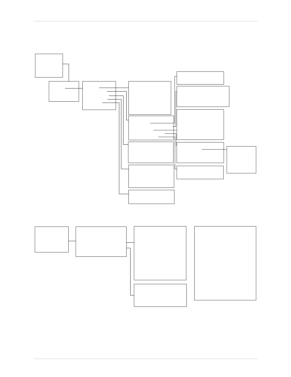
Overview of menu operations, Figure 3-2. main menu > configuration > system – RAD Data comm IPmux-11 User Manual
Page 56
Chapter 3 Operation
Installation and Operation Manual
3-10
Configuration Alternatives
IPmux-11 Ver. 2.00
Overview of Menu Operations
Use these menu trees as a reference aid while performing configuration and
control functions.
illustrates menus and explains parameters.
Host IP
Management
User Access
1. Device info
2. Authentication/community
3. Manager list
4. Management access
5. Alarm trap mask
1. User name
2. Permission
3.
Access
4. 'su' password
5. New password
6. Confirmation
Authentication/Community
1. System name
2. System location
1. Authentication failure trap
2. Trap
3. Read
4. Write
Manager List
Management Access
Alarm Traps Mask
1. Manager IP address
2. Manager location
3. Link up/down trap
4. Alarm trap
5. VLAN tagging
6. VLAN ID
7. VLAN priority
1. User access
2. Telnet access
3. Web access
1. Alarm ID
2. Trap status
Device Info
1. IP address
2. IP mask
3. Default gateway
4. DHCP
5. DHCP status
Server ID
Lease expiration time
Current status
Control Port
Date/Time
1. Set time
2. Set date
Data bits
Parity
Stop bits
Flow control
1. Baud rate
System Clock
1. Master clock
2. Master source
3. Fall back clock
4. Fall back source
System
1. Host IP
2. Management
4. Control port
5. Date/time
6. Factory default
3. System Clock
Configuration
1. System
2. Physical Layer
3. Connection
4. Bridge
Main Menu
1. Inventory
2. Configuration
3. Monitoring
4. Diagnostics
5. Utilities
4. Snmp access
Figure 3-2. Main Menu > Configuration > System
TDM (E1)
O
r
TDM (T1)
1. Admin status
2. Transmit clock source
3. Rx sensitivity
5. Line type
1. Admin status
2. Transmit clock source
3. Rx sensitivity
5. Line type
6. Line code
7. Line interface
8. Line length or Line BildOut
9. Restoration time
10. Idle code
11. Send upon fail
12. OOS code
13. Signaling mode
14. OOS signaling
15. Mark signaling code
16. Space signaling code
ETH
1. Channel state
2. Auto negotiation
3. Max capability advertised
4. Default type
6. Idle code
7. Send upon fail
8. OOS code
9. OOS signaling
10. Mark signaling code
11. Space signaling code
4. Trail Mode
4. Trail Mode
1. Admin status
2. Transmit clock source
3. Rx sensitivity
Configuration
1. System
2. Physical layer
3. Connection
4. Bridge
1. TDM interface type
Physical Layer
2. TDM
3. ETH
4. External Clock
Figure 3-3. Configuration > Physical Layer > TDM and ETH Configuration