Chapter 3. operation, 1 turning ipmux-11 on, 2 controls and indicators – RAD Data comm IPmux-11 User Manual
Page 47: Chapter 3, Fer to, For the operating instructions, Chapter 3 operation
IPmux-11 Ver. 2.00
Controls and Indicators
3-1
Chapter 3
Operation
This chapter:
• Provides a detailed description of the front panel controls and indicators and
their functions
• Explains power-on and power-off procedures
• Provides instructions for configuration using a terminal connected to the
IPmux-11 control port
• Provides instructions for configuration using a Web browser
• Illustrates the management menus.
For a detailed explanation of parameters on the menus, see
3.1
Turning IPmux-11 On
To turn on IPmux-11:
• Connect the power cord to the mains.
The PWR indicator lights up and remains lit as long as IPmux-11 receives
power.
Once it is powered up, IPmux-11 operates automatically. IPmux-11 requires no
operator attention once installed, with the exception of occasional monitoring of
front panel indicators. Intervention is only required when IPmux-11 must be
configured to its operational requirements, or diagnostic tests are performed.
3.2 Controls
and
Indicators
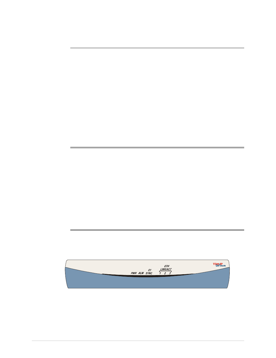
The unit's LEDs are located on the front and rear panels (see
).
lists the functions of the IPmux-11 LED indicators.
IPmux-11
®
Figure 3-1. IPmux-11 Front Panel