Figure 3-4. configuration > connection and bridge, Figure 3-5. monitoring – RAD Data comm IPmux-11 User Manual
Page 57
Installation and Operation Manual
Chapter 3 Operation
IPmux-11 Ver. 2.00
Configuration Alternatives
3-11
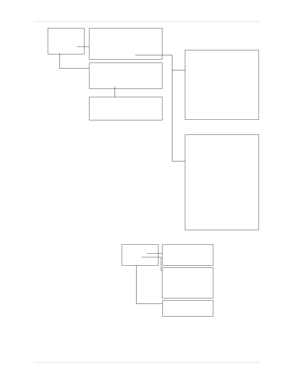
Configuration
Connection
Bundle Connection
1. System
2. Physical layer
3. Connection
4. Bridge
1. Bundle ID
2. DS0 bundle
3. Bundle connection
1. Destination IP address
2. Next hop
3. IP TOS
4. Connection status
5. Destination bundle
6. TDM bytes in frame(x48 bytes)
7. Payload format
8. OAM connectivity
9. Jitter buffer [msec]
10. OOS mode
11. VLAN tagging
12. VLAN ID
13. VLAN priority
Bridge
1. Aging time
2. Erase MAC table
3. Bridge policy
4. VLAN table
VLAN Table
1. Channel
2. VLAN ID
3. Status
2. Connection Mode
3. PSN Type
when Connection Mode=TDMoIP CE,
PSN Type=UDP/IP
Bundle Connection
when Connection Mode=TDMoIP CE,
PSN Type=MPLS/ETH
1. Destination IP address
2. Outbound label tagging
3. Outbound tunnel label
4. Outbound EXP bits
5. Inbound label tagging
6. Inbound tunnel label
7. Connection status
8. Destination bundle
9. Next hop type
10. Next hop IP address
11. TDM bytes in frame(x48 bytes)
12. Far end type
13. OAM connectivity
14. Jitter buffer [msec]
15. Sensitive
16. OOS mode
17. VLAN tagging
18. VLAN ID
19. VLAN priority
Figure 3-4. Configuration > Connection and Bridge
Monitoring
Statistics
Status
1. Statistics
2. Status
3. Event log
1. TDM physical layer
2. Connection
3. Bridge
1. Diagnostics loopback
4. Connection
Event Log
1. Read log file
2. Clear log file
3. ETH Physical layer
5. System Clock
2. TDM Physical layer
Figure 3-5. Monitoring