Appendix a. connector wiring, A.1 e1 and t1 connector, Balanced connector – RAD Data comm IPmux-11 User Manual
Page 125: Balanced-to-unbalanced adapter cable, Refer to, Appendix a, Cable (see, Fer to, Appendix a connector wiring
IPmux-11 Ver. 2.00
E1 and T1 Connector
A-1
Appendix A
Connector Wiring
A.1 E1 and T1 Connector
Balanced Connector
The E1 and T1 interfaces of IPmux-11 terminate in an 8-pin RJ-45 connector,
wired in accordance with
.
Table A-1. E1/T1 Port Connector Pinout
Pin Designation Direction
Function
1
RD (R)
Input
Receive data (ring)
2
RD (T)
Input
Receive data (tip)
3, 6
–
–
FGND
4
TD (R)
Output
Transmit data (ring)
5
TD (T)
Output
Transmit data (tip)
7, 8
–
N/A
Not connected
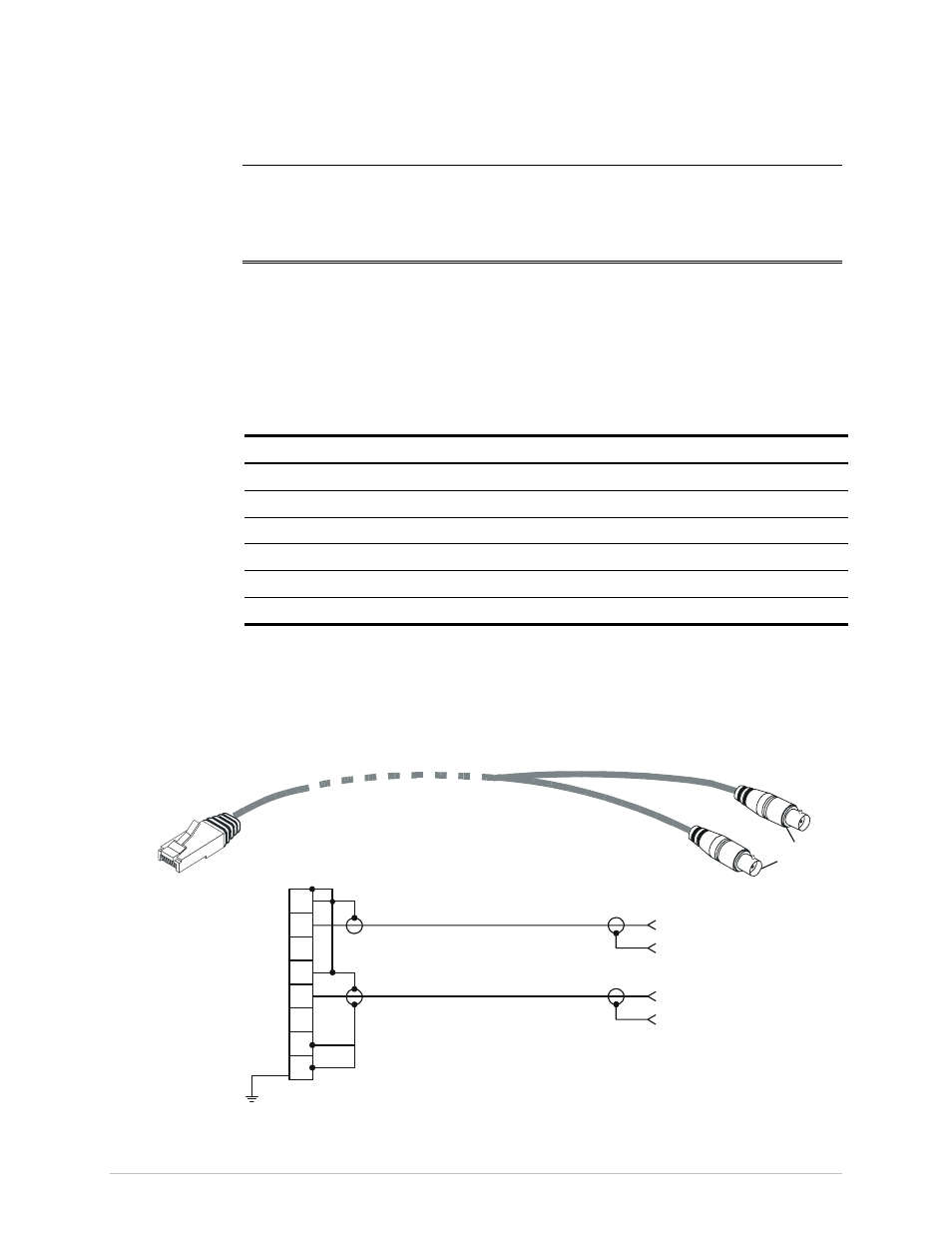
Balanced-to-Unbalanced Adapter Cable
When IPmux-11 is ordered with unbalanced E1 interface, it is necessary to convert
the RJ-45 connector to the standard pair of BNC female connectors used by
unbalanced E1 interfaces. For that purpose, RAD offers a 150-mm long adapter
cable, CBL-RJ45/2BNC/E1/X, wired in accordance with
RJ-45
BNC
Female
Receive
(Green)
Transmit
(Red)
1
2
3
4
5
6
7
8
Shielded
RJ-45
Transmit
(Red BNC)
Receive
(Green BNC)
RX Ring
RX Tip
NC
TX Ring
TX Tip
NC
NC
NC
.
.
.
.
.
.
Figure A-1. CBL-RJ45/2BNC/E1/X Cable Wiring Diagram