1 hssi interface specifications – Mocomtech CDM-QX User Manual
Page 61
CDM-Qx/QxL Multi-Channel Satellite Modem with DoubleTalk™ Carrier-in-Carrier® Revision
7
Rear Panel Connectors
MN/CDMQX.IOM
3–11
3.3.6.1 HSSI Interface Specifications
Item
Requirement
Data Rate Range
32 to 20 Mbps
Signals Supported
ST, TT (or external) , SD, TA, CA, RT, RD, SG
Connector
DCE, 50-pin mini-D female per EIA-613 (HSSI)
Electrical
Per EIA-612 (10KH ECL compatible).
Electrical Typical
Differential output voltage: > 590 mV pp into 110 load
Differential Input voltage: 150 to 1000 mV pp with 110 load
Minimum Buffer Size
5.0 mS smallest buffer setting, 0.1 mS step size, 32 mS maximum size
Impedance
Tx
110
Ω for TT, SD, TA
Rx
ST, CA, RT, RD will drive 110
Ω and meet HSSI voltage levels
Signal Characteristics
The A terminal is negative with respect to the B terminal for a binary 0 (Space or OFF)
state.
The A terminal is positive with respect to the B Terminal for a binary 1 (Mark or ON)
state.
Clock / Data
Relationship
The data transitions occur during the OFF to ON transition of the clock. Data is stable
during the ON to Off transition of the clock.
Tx Clock Modes
TT (Input clock) continuous.
ST (output clock) is continuous output, programmable in 1 bps steps or phase locked
to satellite clock
Rx Clock Modes
RT (output clock) is continuous from satellite, ST (internal clock), continuous from TT
Tx / Rx Clock
Asymmetrical clocking with Rx Doppler buffer disabled
TA / CA
Default
CA looped to TA
Selection CA is asserted when there is no modem fault
Operation
Simplex (Tx only or Rx only) or full duplex
Signal Sense
Programmable Normal or Inverted or TT and TD, RT and RD
Cable Length to 20
Mbps
2 M (6 ft) nominal, up to 15 M (49 ft) maximum – note higher data rates usually
require shorter cable lengths
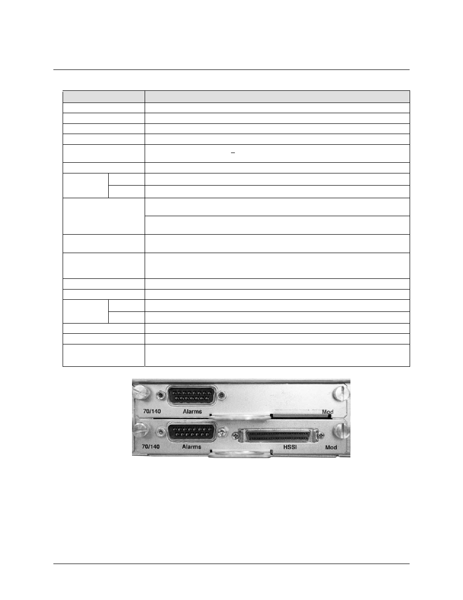
Figure 3-3. HSSI Interface Example