5 quad e1 data interface connectors – Mocomtech CDM-QX User Manual
Page 59
CDM-Qx/QxL Multi-Channel Satellite Modem with DoubleTalk™ Carrier-in-Carrier® Revision
7
Rear Panel Connectors
MN/CDMQX.IOM
3–9
3.3.5
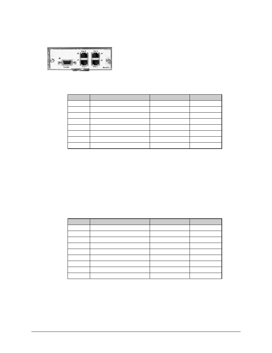
Quad E1 Data Interface Connectors
The Quad E1 Data interface card allows the user to connect
one to four different terrestrial E1 ports, with each port
independently configurable for full E1 (framed or unframed E1
data), or fractional E1 (with D&I). These four RJ-45 ports –
labeled J1 Port 1 through J4 Port 4, respectively, on the
interface card – must be synchronized to each other.
Table 3-6. Quad E1 Data Interface J1-J4 Connector Pin Assignments
Pin #
Signal Function
Name
Direction
1 DDI
(+)
Port_Tx+ In
2 DDI
(-)
Port_Tx– In
3 Ground
Gnd
--
4 IDO
(+)
Port_Rx+ Out
5 IDO
(-)
Port_Rx– Out
6 Ground
Gnd
--
7 Unused
NC
--
8 Unused
NC
--
The J5 Ext Ref connector is a 9-pin Type ‘D’ female (DB-9F) connector on the interface card that
provides two functions:
1. The first function is to provide an output E1 clock for the user to use as an E1 clock
reference (if needed for the terrestrial E1 equipment).
2. The second purpose of the connector is to allow the user to provide a reference E1 input
clock. The user can then use this E1 clock input to drive the demodulator receive buffer.
Refer to Chapter 5. FRONT PANEL OPERATION, in particular the section outlining
Config
Æ Rx Æ Buf Æ RX BUFFER CLOCK SOURCE
, for further information.
Table 3-7. Quad E1 Clock Interface J5, DB-9F Connector Pin Assignments
Pin #
Signal Function
Name
Direction
1
E1 Clk Ref Out (-)
E1 Clk Out (-)
Out
2 Unused
NC
--
3 Ground
Gnd
--
4 Unused
NC
--
5
E1 Clk Ref In (+)
E1 Clk In (+)
In
6
E1 Clk Ref Out (+)
E1 Clk Out (+)
Out
7 Unused
NC
--
8 Unused
NC
--
9
E1 Clk Ref In (-)
E1 Clk In (-)
In