Chapter 3. rear panel connectors, 1 connector overview – Mocomtech CDM-QX User Manual
Page 51
3–1
Slot 1
Slot 2
Slot 3
Slot 4
IF I/O
Prime Power & Control
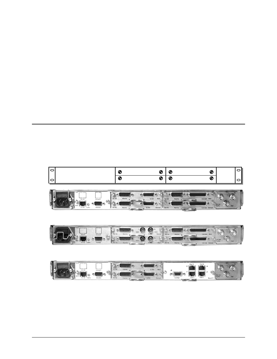
Configuration #1
Modem 1 with G.703 T1/E1 Balanced (DB-15)
Modem 2 with EIA-422 (DB-25)
Configuration #2
Modem 1 with G.703 T1/E1 Unbalanced (BNC)
Modem 2 with EIA-422 (DB-25)
Configuration #3
Modem 1 with G.703 T1/E1 Balanced (DB-15) and
Quad E1 Interface Module, 1-4 Ports of E1, with D&I (4) RJ-45
Chapter 3. REAR PANEL
CONNECTORS
3.1
Connector Overview
The CDM-Qx/QxL Multi-Channel Satellite Modem rear panel can be customized to meet user
requirements. As per the three configuration examples shown here in Figure 3-1, optional data
interface modules, used in tandem with the base chassis connectors, provide all necessary
external connections between the modem and other equipment.
Figure 3-1. CDM-Qx/QxL Rear Panel Configuration Examples