5 cnc carrier offset – Mocomtech CDM-QX User Manual
Page 196
CDM-Qx/QxL Multi-Channel Satellite Modem with DoubleTalk™ Carrier-in-Carrier® Revision
7
DoubleTalk™ Carrier-in-Carrier® (CnC)
MN/CDMQX.IOM
9–10
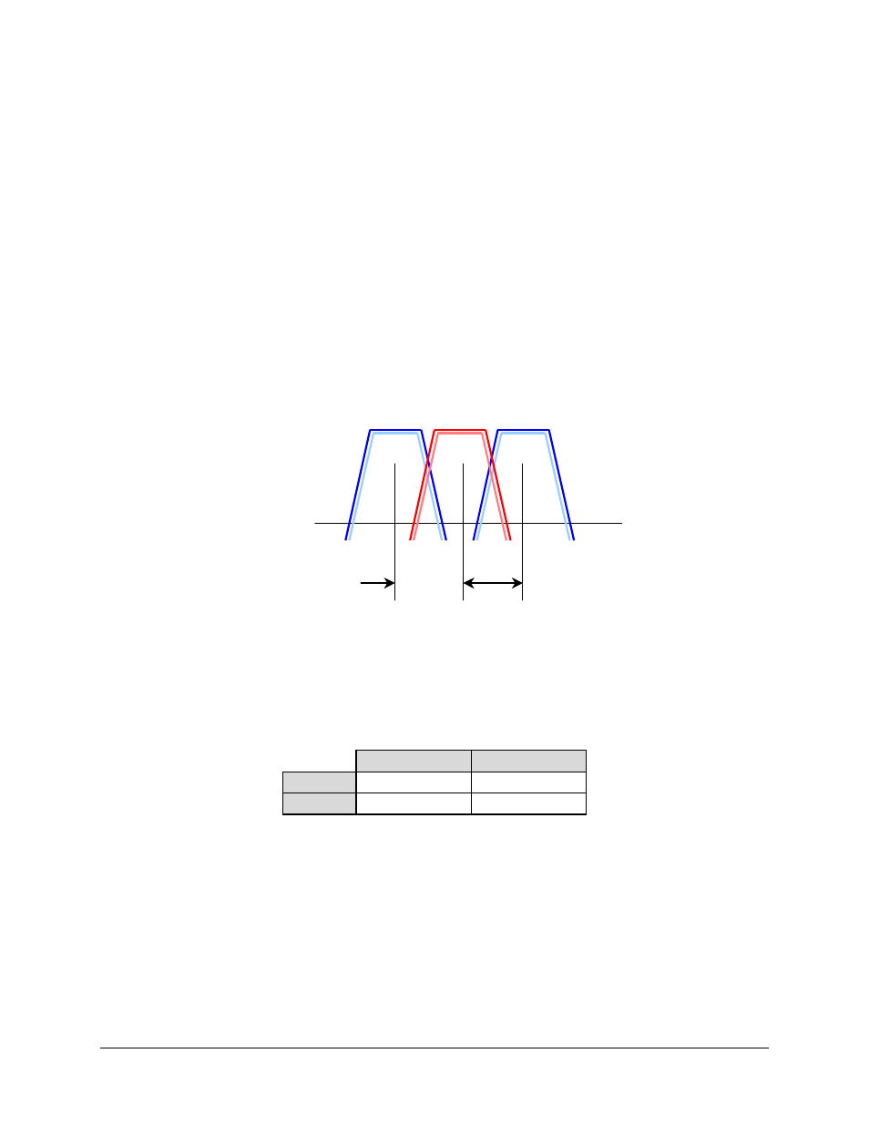
Desired
Carrier(s)
Carrier
Spacing
9.4.5
CnC Carrier Offset
CnC carriers are normally placed directly on top of each other with the same center frequency for
both carriers. Normal operation is obtained when the center frequency of the two carriers is
within
± 32 kHz. This is the same as the normal acquisition range of the modem for standard and
CnC carriers.
9.4.6
1
st
CnC Example: Adjacent Carriers, CnC Ratio and Rain Fade
As an example, a pair CnC carriers is flanked by two adjacent CnC pairs with a carrier spacing of
1.3 x Symbol Rate and the power level is the same for all carriers as shown in Figure 9-11. In
this scenario, the modulation is 8-PSK 3/4 Turbo with identical data rates. The degradation due to
adjacent carrier spacing is negligible when spacing is 1.3 x Symbol Rate and 0dB is allocated for
adjacent carrier degradation.
Figure 9-11. CnC Example
Initially, the CnC ratio is 0dB and the desired and interfering carriers are operating at the same
power level. At one end of the link (Site ‘A’), a downlink fade of 4dB is expected and an uplink
fade of 6dB. The other end of the link (Site ‘B’) is allocated 2dB for downlink and 3dB for the
uplink:
Site ‘A’
Site ‘B’
DL Fade
4dB 2dB
UL Fade
6dB 3dB
When a rain fade occurs at one site, the effect is felt at both sites as illustrated on the next page in
in , which diagrams the worst case fade at Site ‘A’. The interfering carrier at Site ‘A’ is
attenuated twice, once due to the uplink and the second time due to the downlink on the return
path. The carrier transmitted from Site ‘B’ sees only the downlink fade when it is received at
Site ‘A’. The resulting power level changes at each site due to the rain fade and the resulting CnC
ratio and Eb/No degradation is summarized in Table 9-1.