2 rear panel – Mocomtech CDM-QX User Manual
Page 31
CDM-Qx/QxL Multi-Channel Satellite Modem with DoubleTalk™ Carrier-in-Carrier® Revision
7
Introduction
MN/CDMQx.IOM
1–7
Note: As shown in Figure 1-4, units manufactured prior to June 2007 featured six
individual keyswitches mounted behind a fully sealed membrane overlay.
These six switches are identified (in Current Keypad [Earlier Keypad] format) as S [
↑],
T [
↓], W [←], X [→],
ENTER [ENT],
and
CLEAR [CLR]
.
• The VFD is an active display showing two lines of 40 characters each. It produces a blue
light with adjustable brightness. Compared to a Liquid Crystal Display (LCD), the VFD
has greatly superior viewing characteristics and does not suffer problems of viewing
angle or contrast.
The function and behavior of the LED indicators, keypad, and VFD is described in detail in
Chapter 5. FRONT PANEL OPERATION.
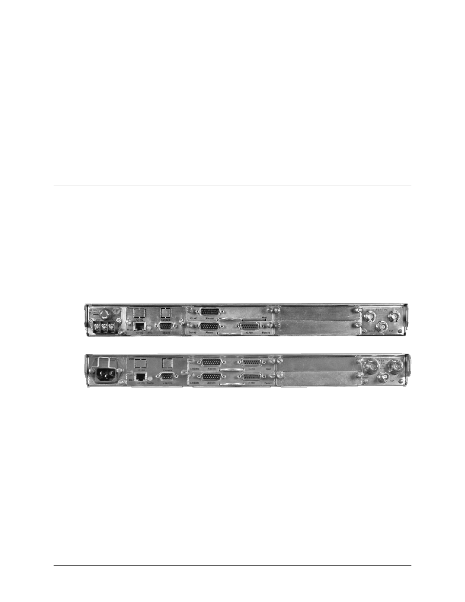
1.3.5.2 Rear Panel
Figure 1-5 shows the connectors installed in the rear panel of the CDM-Qx/QxL Multi-Channel
Satellite Modem. As outlined in A CDM-Qx/QxL base chassis features two IF connectors and
three Utility connectors that are typical for all operation. Additionally, an Alarms connector, not
part of the base chassis but included in this table for reference only, is provided with every
available data interface module.
External cables are attached to these connectors. For detailed information about the connectors
outlined in Table 1-1, plus the connectors unique to each date interface module, see Chapter 3.
REAR PANEL CONNECTORS.
Figure 1-5. CDM-Qx/QxL Rear Panel View
CDM-Qx (70/140 MHz) DC Unit
CDM-QxL (L-Band) AC Unit