Mocomtech CDM-QX User Manual
Page 145
CDM-Qx/QxL Multi-Channel Satellite Modem with DoubleTalk™ Carrier-in-Carrier®
Revision 7
Ethernet Management
MN/CDMQX.IOM
6–15
If no module is installed, the space assigned to that slot will not be visible. For example, the
Configuration Icon Group shown in Figure 6-6 depicts a modulator pair (a Tx module installed in
Slot#1 and an Rx module installed in Slot#2) grouped as a modem; Slots 3 and 4 are empty.
Note: At a minimum, the Base icon is always displayed and selectable.
Furthermore, the Quick View page highlights the active component (i.e., Base, Tx, Rx, or MD).
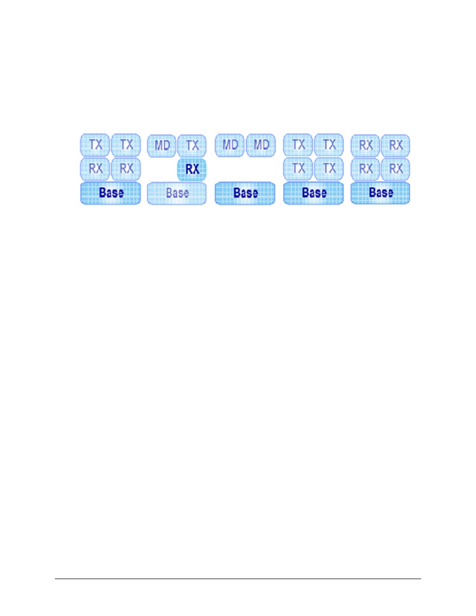
The display may resemble, but is not limited to, the configuration examples shown in Figure 6-7:
Figure 6-7. Configuration Icon Group Examples
To configure a component (Base, Tx, Rx, or MD), click on that icon. At this point, the user may
select one of four configuration tabs available to the right of the Configuration Icon Group (atop
the primary info windows of this interface): Config, Status, Test, or Utility.
The following subsections detail use of these nested pages. The accessibility of content on each of
these nested pages depends on the active component that has been selected from the
Configuration Icon Group:
• If the Base is selected, the common functions of the installed modules (Tx or Rx) are
configurable.
• If a modulator slot (Tx) is selected, only the modulator parameters will be displayed and
accessible.
• If a demodulator slot (Rx) is selected, only the demodulator parameters will be displayed
and accessible.
• If a modem (MD) is selected, both the modulator and demodulator parameters are
accessible.
(4) independant
modules (2 Tx, 2
Rx) present, Base
active
(1) Modem pair,
(2) independant
modules present,
Slot#4 Rx module
active
(2) Modem pair
present, Base
active
(4) independant Tx
modules present,
Base active
(4) independant Rx
modules present,
Base active