3 data interface connectors, 1 typical alarms connector – Mocomtech CDM-QX User Manual
Page 56
CDM-Qx/QxL Multi-Channel Satellite Modem with DoubleTalk™ Carrier-in-Carrier® Revision
7
Rear Panel Connectors
MN/CDMQX.IOM
3–6
either 50
Ω or 75Ω. Input level is 0 dBm minimum to +20 dBm maximum at either 1, 2, 5, 10, or 20
MHz. When external reference is enabled, the internal 10 MHz reference oscillator is phase locked
to the external reference input by a 10Hz bandwidth PLL. If no activity is present at the external
reference input, the modem will revert to the internal 10 MHz reference.
3.3
Data Interface Connectors
3.3.1
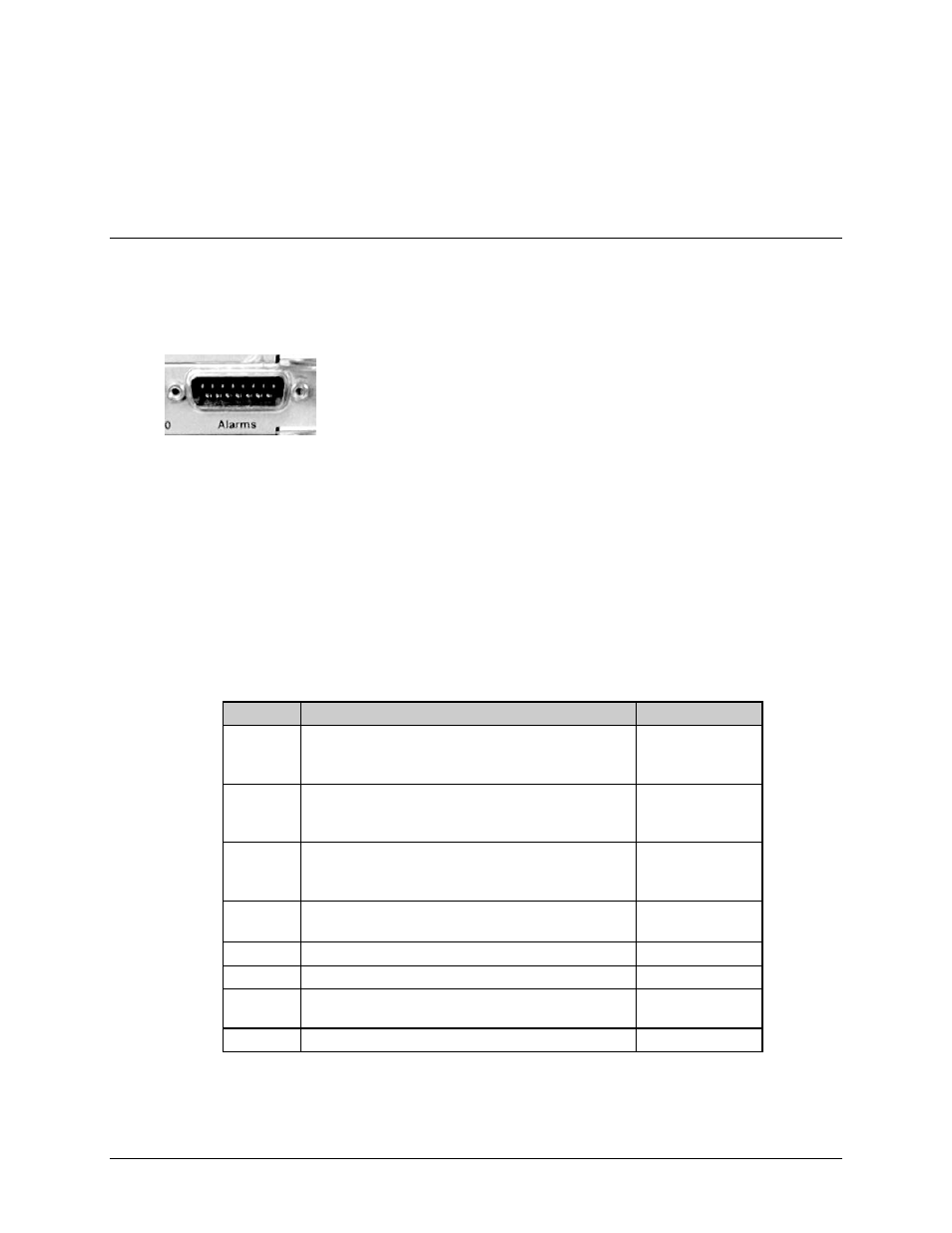
Typical Alarms Connector
All available data interface modules contain a 15-pin 'D' type male
(DB-15M) Alarms connector. The Alarms connector provides the user
with access to the Form-C relay contacts, which indicate the fault status of
the unit. These are typically connected to an external fault monitoring
system, often found in satellite earth stations.
For a Modulator: TX fault and Unit Fault are supported. The transmit I and Q modulator
samples are available on this connector. Connecting these signals to an oscilloscope in X,Y mode
will provide the modulator signal constellation diagram, which is a useful diagnostic aid. A pin
also is provided which can mute the transmit carrier. This requires that the pin be shorted to
ground, or a TTL ‘low’.
For a Demodulator: RX fault and Unit Fault are supported. If a Modulator and Demodulator are
vertically grouped together as a modem, TX fault and the EXT Carrier OFF pin will also be
supported. The receive I and Q demodulator samples are provided on this connector. Connecting
these signals to an oscilloscope in X,Y mode will provide the receive signal constellation
diagram, which is a useful diagnostic aid.
Table 3-3. Alarms Interface Connector Pin Assignments
Pin #
Signal Function
Name
8
15
7
RX Traffic (De-energized, Faulted)
RX Traffic (Energized, No Fault)
RX Traffic
RX-NC
RX-NO
RX-COM
14
6
13
TX Traffic (De-energized, Faulted)
TX Traffic (Energized, No Fault)
TX Traffic
TX-NC
TX-NO
TX-COM
5
12
4
Unit Fault (De-energized, Faulted)
Unit Fault (Energized, No Fault)
Unit Fault
UNIT-NC
UNIT-NO
UNIT-COM
11
3
I Channel (Constellation monitor)
Q Channel (Constellation monitor)
TX or RX-I
TX or RX-Q
10 No
Connection
N/C
2 No
Connection
N/C
9
EXT Carrier OFF (modulator or modulator and
demodulator grouped together)
EXT-OFF
1 Ground
GND