Hardware options, 1 cdm-qx/qxl hardware options – Mocomtech CDM-QX User Manual
Page 32
CDM-Qx/QxL Multi-Channel Satellite Modem with DoubleTalk™ Carrier-in-Carrier® Revision
7
Introduction
MN/CDMQx.IOM
1–8
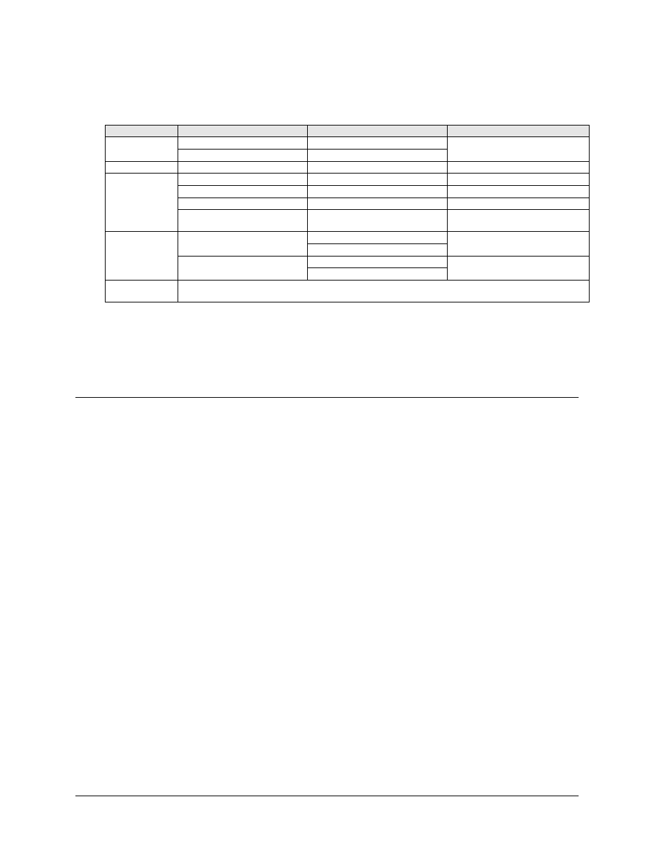
Table 1-1. CDM-Qx/QxL Rear Panel Connectors – Base Chassis
Connector Group
Connector Name
Connector Type
Function
Power (Sect. 3.2.1)
AC
See Sect. 3.5.1
Chassis power
DC (optional, CDM-QxL only)
See Sect. 3.5.2
Ground (Sect. 3.2.2)
#10-32 stud
Common Chassis Ground
Utility
(Sects. 3.2.3, 3.2.4,
3.2.6, 3.3.1)
M&C 10/100 (Sect. 3.2.3)
RJ-45
10/100 BaseT Remote Interface
485/232 (Sect 3.2.4)
9-pin Type ‘D’ female
EIA Remote Interface
Ref (Sect 3.2.6)
BNC 50Ω female
External reference for modem synthesizers
Alarms (not p/o base chassis – typical
for each data interface) (Sect. 3.3.1)
15-pin Type ‘D’ male
Form C Alarms (relay closures)
IF (Sect. 3.2.5)
Rx
CDM-Qx: BNC female (70/140MHz band)
IF Input
CDM-QxL: Type ’N’ female (L-Band)
Tx
CDM-Qx: BNC female (70/140MHz band)
IF Output
CDM-QxL: Type ’N’ female (L-Band)
Terrestrial Data
(Sect. 3.3)
Connectors vary dependant on the installed data interface (G.703 Bal, G.703 Unbal, EIA-530, Quad E1, or HSSI) module.
See Sect. 3.3.x for complete information about the connectors associated with these interfaces.
Note: The European EMC Directive (EN55022, EN50082-1) requires using properly shielded cables for DATA
I/O. These cables must be double-shielded from end-to-end, ensuring a continuous ground shield.
1.3.6
Hardware Options
1.3.6.1 CDM-Qx/QxL Hardware Options
There are four hardware options available:
• The first hardware option, Comtech EF Data’s Turbo Product Codec (TPC), represents
a very significant development in the area of Forward Error Correction (FEC). It provides
one of the best FEC technologies currently available, and is now offered with a sufficient
range of code rates and modulation types to optimize link performance under any
conditions.
Turbo Product Codec consists of a plug-in daughter card (SIMM module) that is field
upgradeable. The TPC option provides data rate capability up to 20 Mbps, with the
following code rates:
o
Rate 5/16 (BPSK)
o
Rate 21/44 (BPSK, QPSK)
o
Rate 3/4 (QPSK, 8-PSK, and 16-QAM)
o
Rate 7/8 (QPSK, 8-PSK, and 16-QAM)
o
Rate 17/18 (QPSK, 8-PSK)
• The second hardware option is the Internal Reference Stability. The high stability
option includes a 6 x 10
-8
10 MHz reference oscillator on the IF Backplane board, while
the low stability option has a 1 x 10
-6
10 MHz reference on the IF Backplane board. This
option must be configured in the factory at the time of order.
• The third hardware option is the IF Impedance and Connectors. The IF may be
configured with either BNC female connectors at 75
Ω impedance, BNC female