4 eia-530 data interface connector – Mocomtech CDM-QX User Manual
Page 58
CDM-Qx/QxL Multi-Channel Satellite Modem with DoubleTalk™ Carrier-in-Carrier® Revision
7
Rear Panel Connectors
MN/CDMQX.IOM
3–8
3.3.4
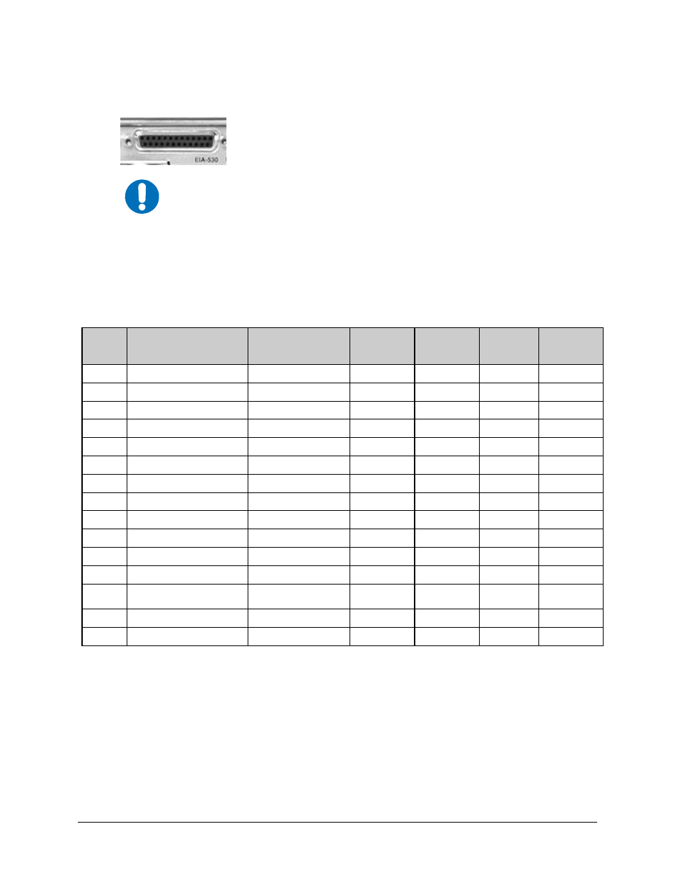
EIA-530 Data Interface Connector
The Data connector is a 25-pin ‘D’ type female (DB-25F). This connector
conforms to the RS-530 pinout, which allows for connection of different
electrical standards, including EIA-422, V.35, and EIA-232.
IMPORTANT
All data interfaces are duplex! They will only operate as duplex if a Modulator
and Demodulator are vertically grouped together as a modem. In that case the
data interface connector on the Demodulator switches to duplex. This feature
allows a single data interface connection to be used for a modem instead of
needing a “Y” cable. Otherwise, the data interface for each module will only
operate as simplex.
It is the responsibility of the user to provide the appropriate cables to connect
to this EIA-530 connector.
Table 3-5. RS-530 Data Interface Connector Pin Assignments
Pin #
Generic Signal
Description
Direction
RS-422
RS- 530
LVDS
V.35
RS-232
Circuit #
2
TX Data A
DTE to Modem
SD A
SD A
BA
103
14
TX Data B
DTE to Modem
SD B
SD B
-
103
24
TX Clock A
DTE to Modem
TT A
SCTE A
DA
113
11
TX Clock B
DTE to Modem
TT B
SCTE B
-
113
15
INT TX Clock A
Modem to DTE
ST A
SCT A
DB
114
12
INT TX Clock B
Modem to DTE
ST B
SCT B
-
114
3
RX Data A
Modem to DTE
RD A
RD A
BB
104
16
RX Data B
Modem to DTE
RD B
RD B
-
104
17
RX Clock A
Modem to DTE
RT A
SCR A
DD
115
9
RX Clock B
Modem to DTE
RT B
SCR B
-
115
8
Receiver Ready A
Modem to DTE
RR A
RLSD *
CF
109
10
Receiver Ready B
Modem to DTE
RR B
-
-
109
23
External Carrier Off
(RS-232 ‘1' or TTL ‘low’ )
DTE to Modem
-
-
-
-
7 Signal
Ground
-
SG SG AB 102
1 Shield
- Shield
FG
AN
101
Notes:
1. Receiver Ready is an RS-232 -level control signal on a V.35 interface.
2. DO NOT connect signals to pins which are not shown - these pins are reserved for use by the redundancy system.
3. ‘B’ signal lines are not used for RS-232 applications.
4. For X.21 operation, use the EIA-422 pins, but ignore RX Clock if the Modem is DTE, and ignore TX clocks if the
Modem is DCE.