O.2 red_state and error_state, Red_state and error_state 139 – FUJITSU Implementation Supplement Fujitsu SPARC64 V User Manual
Page 150
Release 1.0, 1 July 2002
F. Chapter O
Reset, RED_state, and error_state
139
O.2
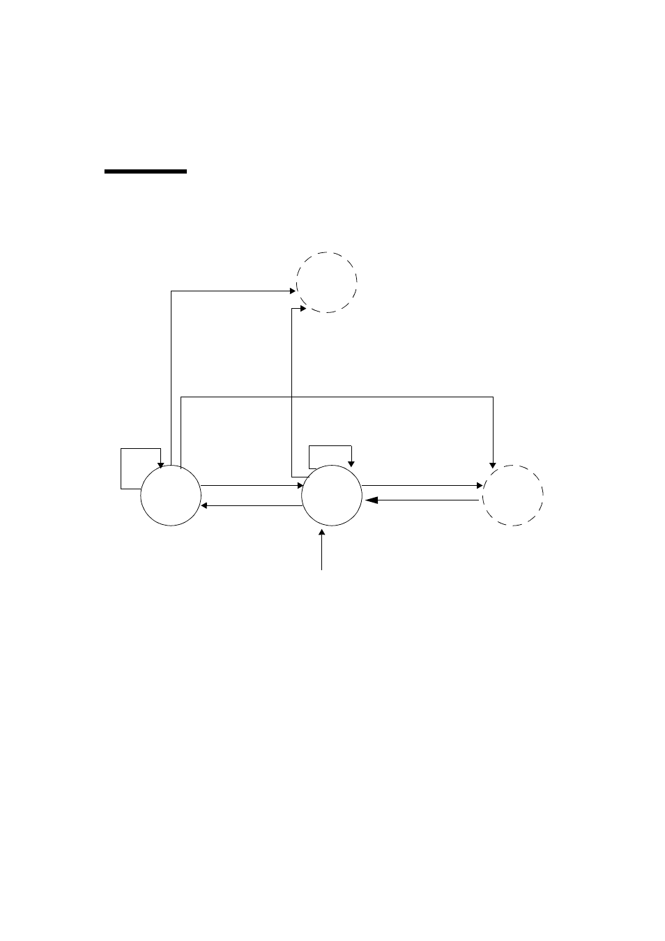
RED_state and error_state
illustrates the processor state transition diagram.
FIGURE O-1
Processor State Diagram
exec_state
RED_state
error_state
**
DONE/RETRY
RED = 0
TRAP@MAXTL–1 TRAP RED = 1 TRAP@MAXTL TRAP@ SIR@ TRAP@MAXTL SIR@MAXTL @ POR WDT1* WDT2** XIR Any State Including Power Off @ WDT1@MAXTL–1 WDT1@ WDT1@MAXTL WDT2* ErrorState trans Error CPU Fatal Error *** Fatal Error Fatal Error * WDT1 is the first watchdog timeout. ** WDT2 is the second watchdog timeout. WDT2 takes the CPU into error_state . In a normal setting, error_state immediately generates a watchdog reset trap and brings the CPU into RED_state . Thus, the state is transient. When OPSR (Operation Status Register) specifies the stop on error_ state , an entry into error_state does not cause a watchdog reset and the CPU remains in the error_state . *** CPU_fatal_error_state signals the detection of a fatal error to the system through P_FERR signal to the sys- tem, and the system causes a FATAL reset. Soft POR will be applied to the all CPUs in the system at the FATAL WDR
SIR@
SIR@MAXTL
reset.