Analog glideslope interface (cat. 9 id 0,1,5) – Honeywell MK VI User Manual
Page 95
Honeywell
MK VI MK VIII EGPWS Installation Design Guide
Proprietary notice on title page applies
CAGE CODE: 97896
SCALE: NONE
SIZE: A
DWG NO: 060-4314-150
REV:
SHEET
95
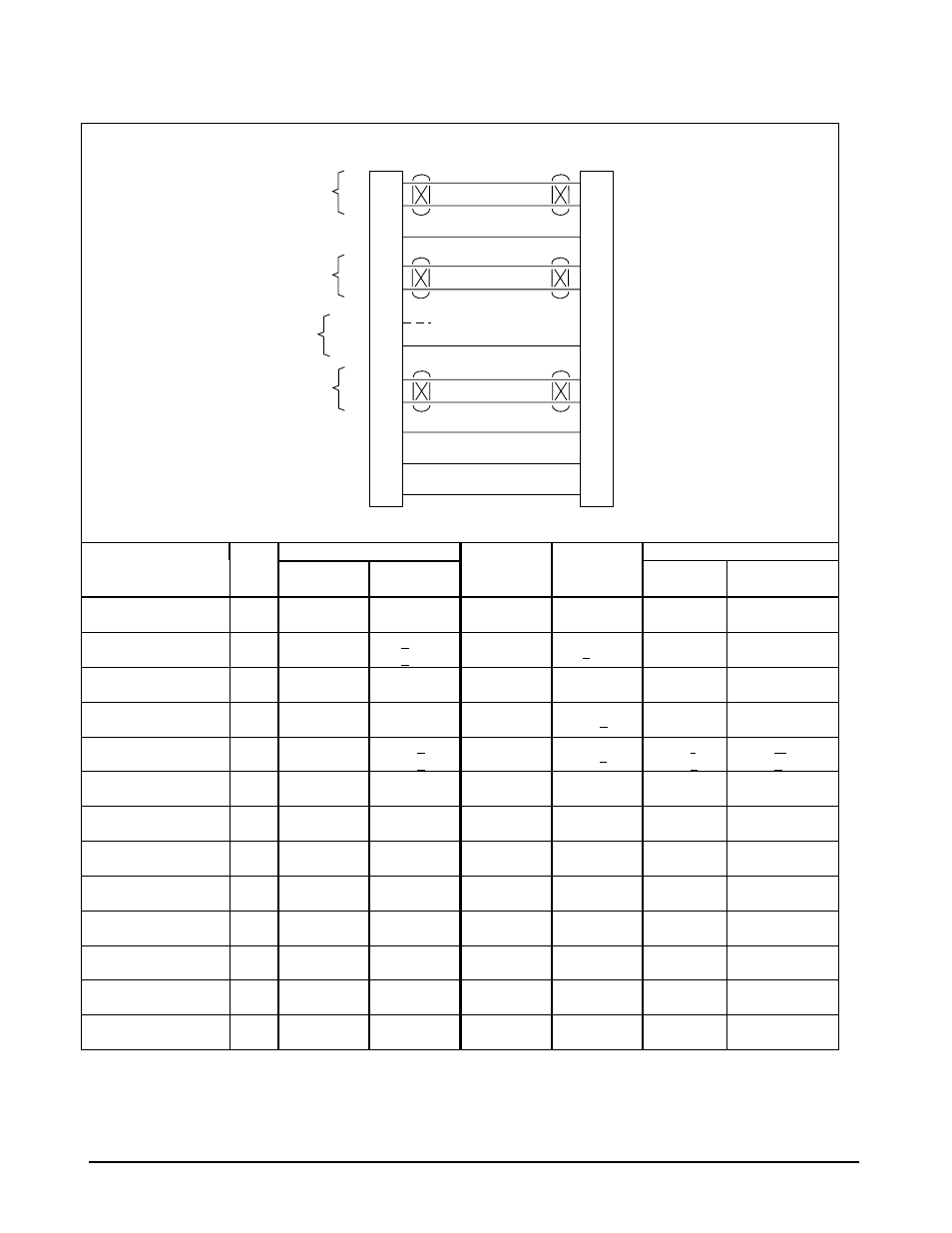
3.11.5 Analog Glid eslope Interface (Cat. 9 ID 0,1,5)
J1
ILS Receiver
EGPWS MK VI / MK VIII
GS Valid +28
11
+
-
Low Level
GS Valid
+28
GND
ILS
Tuned
+
-
GS Deviation
65
46
30
10
39
20
Super Flag +28V
+
-
Delayed ILS Mode
ILS Energize
GS Flag
(Low Level)
+Up
+Dn
GS Deviation
Analog-ILS-1.vsd
LOC Valid +28
48
LOC Val +28V
+
-
LOC Deviation
30
10
+L
+R
LOC Deviation
GS Inhibit (BC) +28
38
Backcourse
GS Inhibit (BC) GND
19
Backcourse
GS Valid
LOC Valid
ILS Tuned
Deviation
Vendor Model
Cat. 9
ID
SuperFlag
+28V
Low Level
Flag
SuperFlag
+28V
GND
GS +up
+dn
LOC +R
+L
Honeywell
KNR 6030
5
J1003-27
J1003-21
J1003-22
J1002-50
J1002-18
J1003-8
J1003-9
J1002-39
J1002-40
Honeywell
KNR 660
1
P1-e
P1-q
P1-k
P1-T
P1-V
Honeywell
KNR 634
1
5
P6342-50
P6342-34
P6342-18
P6342-49
P6341-17
P6342-36
P6342-35
P6342-23
P6342-7
Honeywell
KGM-691
0
P692-W
P692-S
P692-T
P692-a
P692-B
P692-C
Honeywell
KNR 600A
1
P601-e
P601-q
P601-A
P601-k
P601-r
P601-s
P601-m
P601-n
Collins
51RV-1, 51RV-4( )
5
TP-27
2
TP-21
TP-22
BP-50
BP-18
TP-8
TP-9
BP-39
BP-40
Collins
VIR-30, -31, -32
5
P1-17
P1-9
P1-13
P2-18
P2-40
P1-5
P1-1
P2-10
P2-13
Honeywell
VNS 41A
5
P1001-60
P1001-101
J1001-56
J1001-90
J1001-23
J1001-38
J1001-92
Honeywell
RNA-34A
5
TP-27
TP-21
BP-50
BP-18
TP-8
TP-9
BP-39
BP-40
Honeywell
KN 53
1
P2-13
P2-R
P2-12
P2-P
P2-14
Honeywell
KN 72
P1-2
P1-10
Honeywell
RNZ 850
5
P1-A74
P1-B60
P1-B106
P1-B91
P1-B64
P1-B79
P1-B75
P1-B78
P1-B75
Honeywell
KX-155/165
1
P901-U
P901-R
P401-14
P401-8
P901-S
P901-T
P901-s
(KX-165)
P901-k (only
NOTE:
The connector pin numbers given in the Table above are to the best knowledge of Honeywell EGPWS engineering. ePlease
contact the manufacturer’s customer service to confirm your installation.
1
066-1078-00, -01, -04, -05, -10, -11, -14 and –15 only.
2
51RV-4( ) only.