Category 8, radio altitude input select, 8 category 8, radio altitude input select – Honeywell MK VI User Manual
Page 244
Honeywell
MK VI MK VIII EGPWS Installation Design Guide
Proprietary notice on title page applies
CAGE CODE: 97896
SCALE: NONE
SIZE: A
DWG NO: 060-4314-150
REV:
SHEET
244
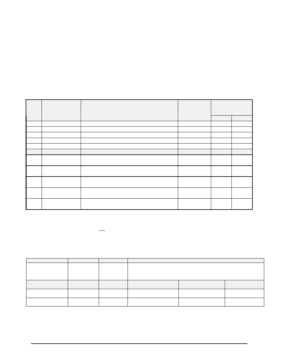
5.3.8 Category 8, Radio Altitude Input Select
The following table provides identification of the Radio Altitude type. The entry in the Radio Altitude Type corresponds
to a table that provides detailed information on the configuration. For example, the details for Radio Altitude Type #1 are
found in Table 5.3.8-1. ARINC 552, ALT 55 and digital ARINC 429 compatible Radio Altimeters are supported. ALT50
Radio Altimeters are not recommended due to the maximum 2000-foot operation. GPWS TSO-C92c requires Mode 1
alert thresholds up to 2450 feet radio altitude.
In this category, only the following signals are defined:
•
Radio Altitude source selection, input scaling, and associated validities.
Table 5.3.8: Radio Altitude Input Select
ID
Radio Altitude
Type
Description
Software
Effectivity
EGPWS
Effectivity
(Table 5.3.8-x)
MKVI
MKVIII
0
0
Analog Radio Altitude (ARINC 552)
-020
X
X
1
1
Analog Radio Altitude (ALT 55)
-020
X
X
2
2
Digital Radio Altitude (ARINC 429)
-020
X
X
3
3
Analog Radio Altitude (RT-200/300)
-020
X
X
4
4
Analog Radio Altitude (KRA 405)
-020
X
X
251
251
Digital Radio Altitude (ARINC 429 via dual IOC
buses with DH/MDA) (Note 1,3)
-020
N/A
X
252
252
Digital Radio Altitude (ARINC 429 via dual IOC
buses) (Note 1,3)
-020
N/A
X
253
253
Digital Radio Altitude (ARINC 429 via dual IOC
buses with DH discrete) (Note 1)
-020
N/A
X
254
254
Digital Radio Altitude and MDA (ARINC 429
via dual IOC buses) (Notes 1, 2, 3)
-020
N/A
X
255
255
Digital Radio Altitude (ARINC 429 via dual IOC
buses) (Note 1, 3)
-020
N/A
X
Note 1: ID 251 - 255 may only be used in conjunction with other IOC bus selections for categories 2,6,9,10,11 and 12.
Note 2: ID 254 must be used in conjunction with Category 9 ID 254, since this provides Label 163 which determines from
bits 19-21 whether MDA or DH is displayed.
Note 3: ID 251, 252, 254 and 255 must not be used in conjunction with Category 4, ID 100 or 101 Altitude Callouts types.
Table 5.3.8-0: Radio Altitude Input Select Type 0 (ARINC 552)
SIGNAL
CONNECTION
REFERENCE
SUMMARY DATA
Radio Altimeter #1
(+) = J1-64
(-) = J1-45
6.1.1
4.2.3.1
Format: ARINC 552 with Validity Flag
Input Type: Basic
Fault Designation: RADIO ALTIMETER FAULT
Validity: Radio Altitude Valid Discrete #1 (+28V)
PIN FUNCTION
CONNECTION
PIN TYPE
CHANNEL DESIGNATION
REFERENCE
Polarity/Configuration
References
Radio Altitude Validity
Discrete #1 (+28V)
J1-29
Input
28V_DISC_07
>+17V = Valid
<+4.4V = Invalid
6.6.1
4.2.7
DH Discrete (Gnd)
J1-33
Input
GND_DISC_11
Gnd = Below DH
6.6.14
4.2.7