Serial control interface (sci) status word 1 (ff) – Honeywell MK VI User Manual
Page 296
Honeywell
MK VI MK VIII EGPWS Installation Design Guide
Proprietary notice on title page applies
CAGE CODE: 97896
SCALE: NONE
SIZE: A
DWG NO: 060-4314-150
REV:
SHEET
296
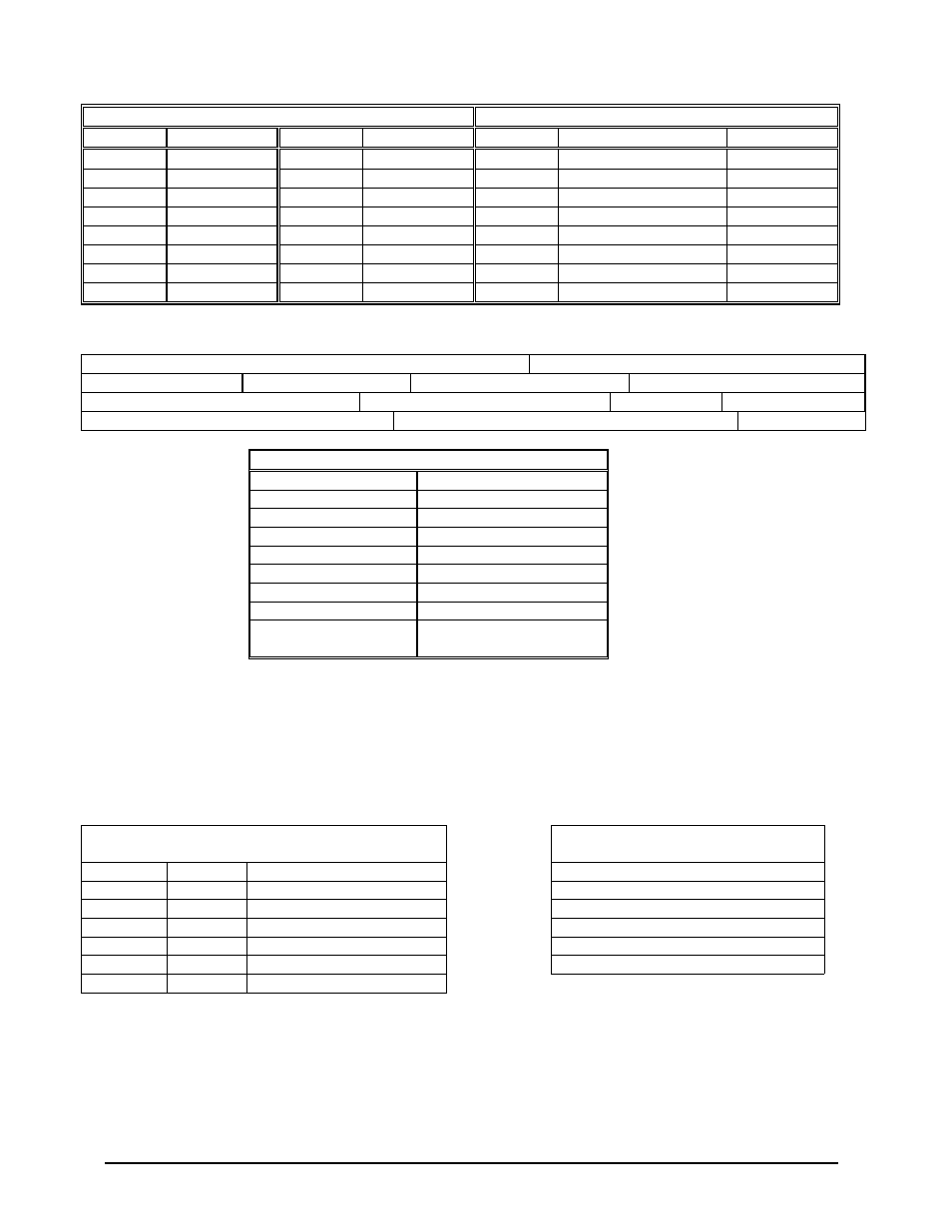
DISPLAY RANGE BIT ASSIGNMENTS
DISPLAY MODE BIT ASSIGNMENTS
1
Bits 4 - 7
Range
Bits 4 - 7
Range
Bits 1-3
Display Mode
Displayable
0100
0.5 NM
0110
150 NM
000
STBY
NO
0010
1.0 NM
1100
200 NM
001
WX
YES
1111
2.5 NM
1010
300 NM
010
MAP
NO
1011
5.0 NM
0001
500 NM
011
FLIGHT PLAN
NO
1101
10 NM
0101
1000 NM
100
TEST
NO
1001
25 NM
0011
2000 NM
101
WX/T
YES
1110
50 NM
0000
spare
110
CYC
NO
1000
100 NM
0111
spare
111
TRB
NO
1
Display Mode used for “bolt-on” EDZ displays only.
6.5.1.2 Serial Control Interface (SCI) Status Word 1 (FF)
Status Word 1
Source: Map Electronics Unit (MEU)
LABEL (Hex) FF
Units: N/A
Max. Range: N/A
Approx. LSB: N/A
Data Bit: 1 – 8
+ = N/A
Sign Bit: N/A
Pad Bits: N/A
Transmit Interval (mSec): See above
Data Type: Discrete
SDI Bits: N/A
STATUS WORD BIT ASSIGNMENTS
BIT
DEFINITION
1
SECTOR SCAN *
2
TARGET ENABLE
3
P-450
4
ERASE
5
VAR GAIN
6
SLAVE
7
RIGHT
8
0
(Always zero in data word)
* Sector Scan used for “bolt-on” EDZ displays only.
6.5.2 Honeywell RS-232 Serial Control Interface for DC811 Up/Down Range
The DC811 controller transmits a 6 byte data packet with spacing between bytes of 16.67 mSec. Each byte consists of one
start bit (low), 8 data bits with least significant bit (LSB) first; an EVEN parity bit and one stop bit (high). The LSB of the
first packet byte is set to 1 to indicate the start of the packet (the other 5 bytes will have the LSB set to 0). The data rate for
this bus is 7.8125 KBS
±
0.01%. Depressing the Up or Down Range button will cause an Up or Down Range bit to be set
for 1 packet period (approximately 100 mSec). After an Up or Down transition no additional changes will be allowed for
approximately ½ second.
DC811 Data Packet
EGPWS Up/Down Ranges Supported
in Nautical Miles
BYTE
BIT
DESCRIPTION
2.5
1
0
1=Start of packet flag
5
2
10
3
25*
4
6
1=Range increment
50
5
1
1=Range decrement
100
6
* (default on power up)