Honeywell MK VI User Manual
Page 184
Honeywell
MK VI MK VIII EGPWS Installation Design Guide
Proprietary notice on title page applies
CAGE CODE: 97896
SCALE: NONE
SIZE: A
DWG NO: 060-4314-150
REV:
SHEET
184
TABLE 5.3.2-11: AIR DATA INPUT SELECT #11
SIGNAL
CONNECTION
REFERENCE
SUMMARY DATA
Uncorrected Barometric
Altitude
(+) = J1-62
(–) = J1-43
6.1.16
Format: DC with Validity Flag
Input Type: Basic
Fault Designation: BAROMETRIC ALTITUDE FAULT
Validity: Barometric Alt Valid (+28V)
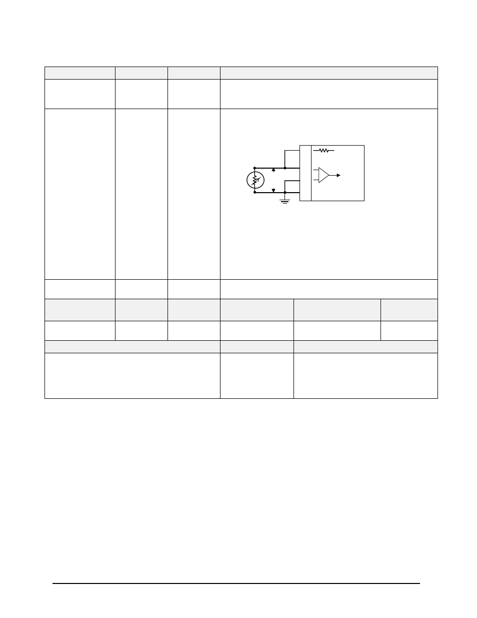
Outside Air Temp
Total Air Temperature
Probe element
Excitation:
Temp Input
(probe element):
Ground
5 V = J1-25
(+) = J1-63
(–) = J1-44
GND = J1-53
6.1.4
4.2.3.5
4.2.10
Format: DC
Input Type: Basic
Fault Designation: STATIC AIR TEMPERATURE FAULT
OAT PROBE
ELEMENT
25
J1
(5 V Ref)
63
44
Temp In
4.42 K Ohms
53
Voat
Chassis Gnd
-
+
Note: Nominal 500
Ω
Temperature Probe only.
Resistance @ 0
°
C: 500
Ω
±
0.6
Ω
Connection example:
CIC Temperature Sensor, P/N 05257 (2 wire). Connect positive
lead to both J1-25 and J1-63. Connect negative lead to both J1-44
and J1-53 (Chassis Ground).
Other probes may have three contacts.
Computed Airspeed
No Connection
N/A
Substitute Ground Speed for Airspeed (airspeed is not available with this air data
input)
PIN FUNCTION
CONNECTION
PIN TYPE
CHANNEL
DESIGNATION
REFERENCE
Polarity/Configuration
References
Barometric Altitude
Validity Discrete (+28V)
J1-9
Input
28V_DISC_08
>+17V = Valid
< +4.4V = Invalid
6.6.22
4.2.7
Configuration Data
Type
Summary Data
Derive Baro Altitude Rate
Analog
Baro Altitude Rate is derived using
Uncorrected Barometric Altitude.
Although the ADC’s provide Baro Rate,
the EGPWS does not have an analog
connection available.