Honeywell MK VI User Manual
Page 219
Honeywell
MK VI MK VIII EGPWS Installation Design Guide
Proprietary notice on title page applies
CAGE CODE: 97896
SCALE: NONE
SIZE: A
DWG NO: 060-4314-150
REV:
SHEET
219
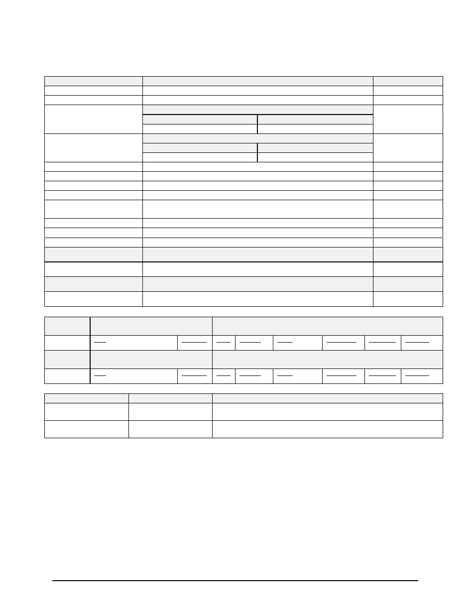
Table 5.3.6.1-236
Collins ProLine 4 (Integrated)
Display Configuration Group 241
Function
Value
Reference section
Display Type
Collins ProLine 4
Sweep Type
Fan Mode with +/-60 degree limit
Category 7, Options Select Group #1
TA&D Alternate Pop Up: False
TA&D Alternate Pop Up: True
Auto Pop Up
Pop Up controlled by display
Pop Up controlled by display
5.3.7
Category 7, Options Select Group #1
Peaks Enabled: False
Peaks Enabled: True
Peaks Mode
Peaks Off
Peaks On
5.3.7
Manual select
Selection is controlled by display
Manual deselect
Deselection is controlled by display
Auto Range
Yes (10 NM) controlled by display
Moving Marker
No
Overlay Page
Yes, “TERR” or Peaks Elevations located on upper left side of Terrain
image. Peaks does not support sea level “blue water”
Display Priority
Standard
Display bus type
ARINC compatible format – Collins ProLine 4 (label 077)
Terrain Mode Annunciation
Standard
DISPLAY BUS #1
453TX_1
CONNECT TO:
A = J1-58
B = J1-59
Terrain Display data to switching relay/Symbol Generator
4.2.13.2
7.2
DISPLAY BUS #2
453TX_2
CONNECT TO:
A = J1-56
B = J1-57
Terrain Display data to switching relay/Symbol Generator
4.2.13.2
7.2
Display Input Control Group 244
CHANNEL
429_422RX_1
CONNECT TO: IOC #1 Bus
Format: ARINC 429 (High Speed)
Fault Designation: IOC BUS 1
Bus Type: Basic
A = J2-37
B = J2-36
Data
Range (Mode/Range Word)
Reference
6.2.21
Label
155
Sig. Bits
Discrete
Range
5-640NM
Signal Type
Basic
Resolution
N/A
Rate (ms)
50
CHANNEL
429RX_3
CONNECT TO: IOC #2 Bus
Format: ARINC 429 (High Speed)
Fault Designation: IOC BUS 2
Bus Type: Basic
A = J2-41
1
B = J2-40
Data
Range (Mode/Range Word)
Reference
6.2.21
Label
155
Sig. Bits
Discrete
Range
5-640NM
Signal Type
Basic
Resolution
N/A
Rate (ms)
50
Output 429 Bus Group 1
Channel
Pins
Comments
429TX_1 (Low Speed)
A = J2-43
B = J2-42
Transmits (Section 7) Label sets: 7.1.1.x, 7.1.2.x, 7.1.3.x, 7.1.4.x, and 7.1.5.x
429TX_2 (Low Speed)
A = J2-26
B = J2-9
Transmits (Section 7) Label sets: 7.1.1.x, 7.1.2.x, 7.1.3.x, 7.1.4.x, and 7.1.5.x
Integration Notes:
When interfacing to a single display controller configuration the bus must be connected to both EGPWS input channels.
This prevents the EGPWS from reporting an external bus fault on the second channel.