3 views, Traverse path display, 3 v iews 6.3 views – HEIDENHAIN SW 68894x-02 User Manual
Page 473
HEIDENHAIN CNC PILOT 640
473
6.3 V
iews
6.3 Views
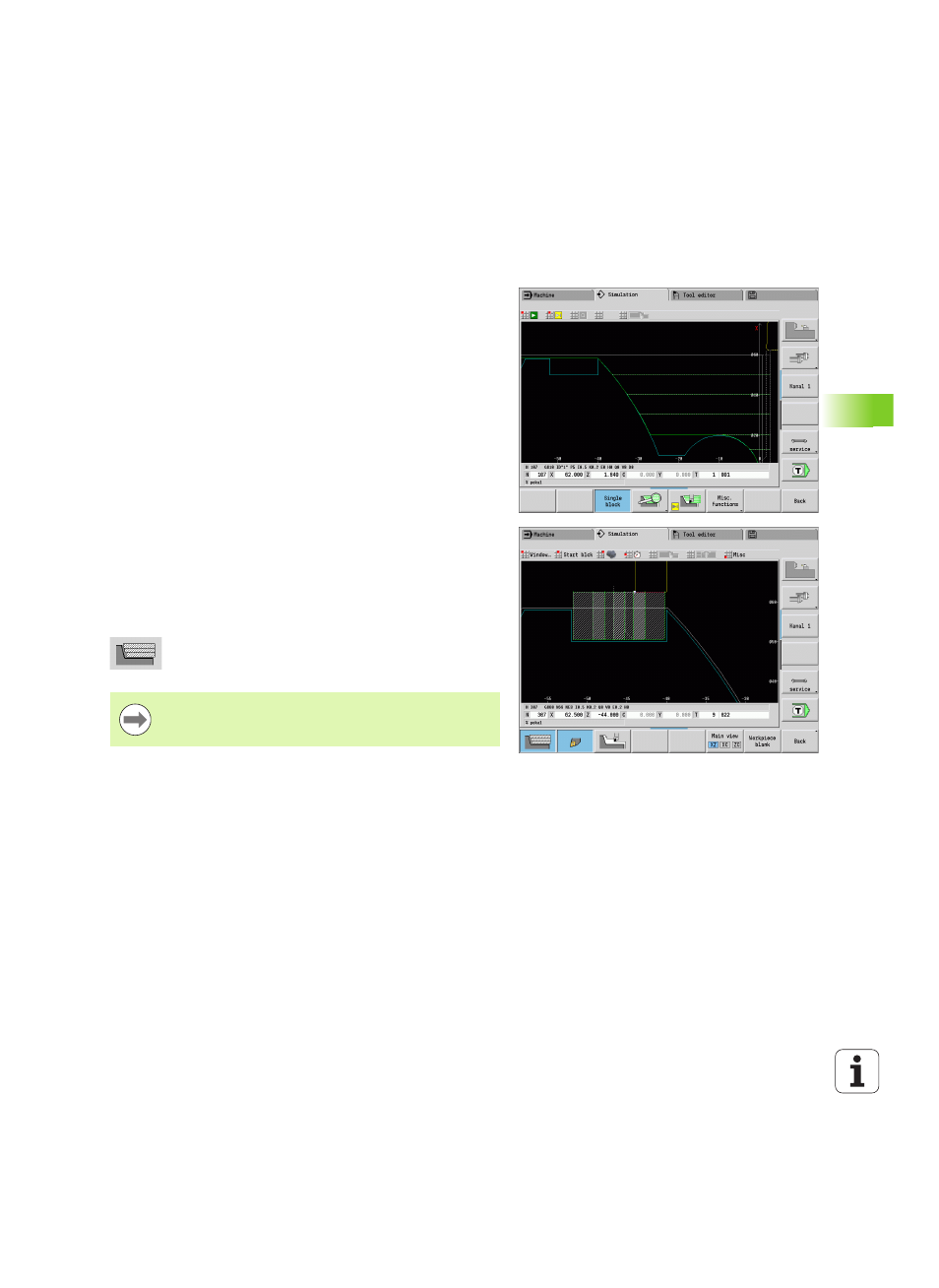
Traverse path display
Rapid traverse paths
are shown as a broken white line.
Feed paths
are displayed either as a line or as a cutting trace,
depending on the soft-key setting:
Line display:
A solid line describes the path of the theoretical tool
tip (wire-frame graphics) The wire frame display is particularly
convenient if you only need a quick overview of the proportioning of
cuts. The path of the theoretical tool tip, however, is not identical
with the contour of the workpiece. This view is therefore not as
suitable if you wish to run a thorough check of the machined
contour. In the CNC, this "falsification" is compensated by the
cutting radius compensation.
Cutting path display:
The simulation uses hatch marking to depict
the surface covered by the cutting area of the tool. The cutting path
graphic accounts for the exact geometry of the tool tip (cutting
radius, cutting width, tool-tip position, etc.). You can check in the
simulation whether the contour is machined completely or needs to
be reworked, whether the contour is damaged by the tool or
overlaps are too large. The cutting path graphics is especially useful
for recessing or drilling operations as well as for machining slopes
where the tool shape has an essential influence on the accuracy of
the resulting workpiece.
Activating the cutting path graphics:
With the soft key activated, the cutting paths of
traverse are shown.
The "Simulation/General settings/Traverse delay" user
parameters are used to influence the simulation speed.