2 simulation window, Setting up the views, See "simulation – HEIDENHAIN SW 68894x-02 User Manual
Page 471: 2 simulation windo w 6.2 simulation window
HEIDENHAIN CNC PILOT 640
471
6.2
Simulation
windo
w
6.2 Simulation window
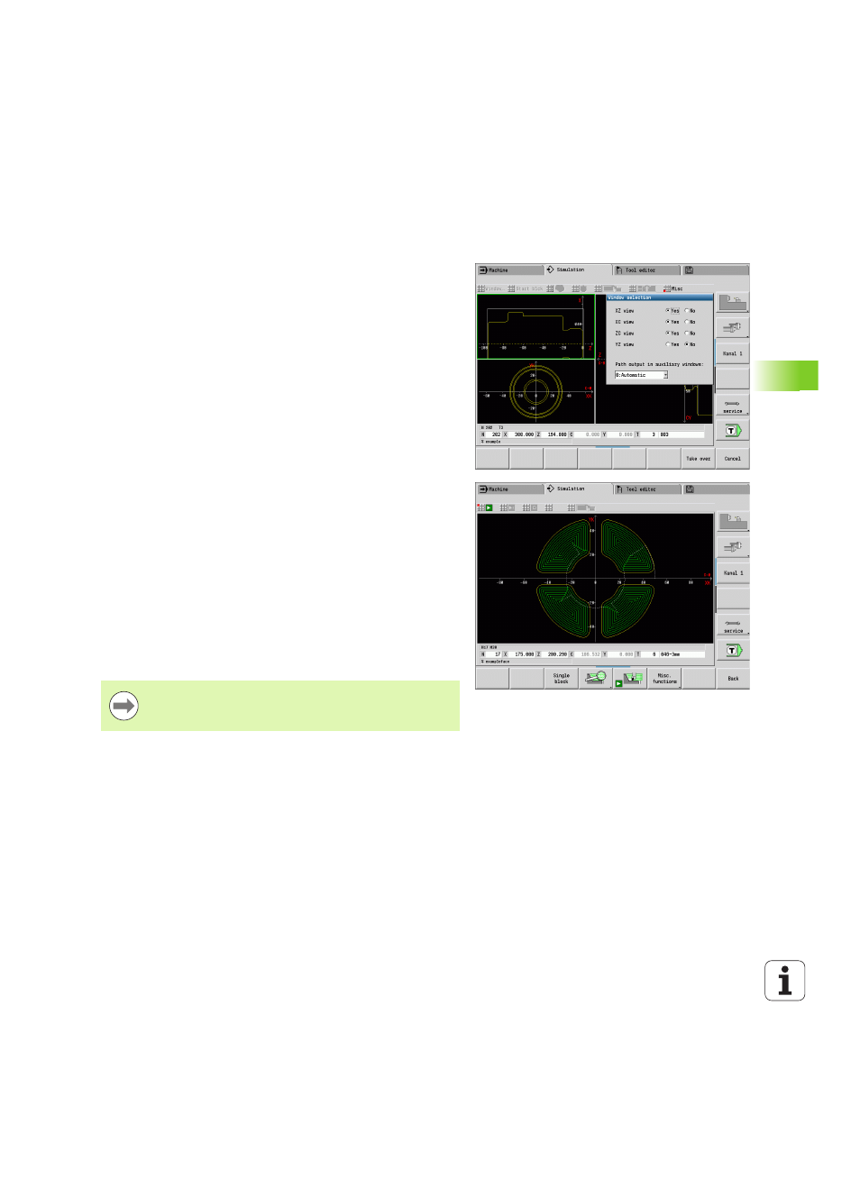
Setting up the views
With the simulation windows described in the following you check not
only the turning work but also the drilling and milling operations.
XZ view (turning view):
The turning contour is depicted in the XZ
coordinate system. The configured coordinate system is taken into
account (tool carrier in front of/behind the turning center, vertical
lathes).
XC view (face view):
The displayed coordinate system is displayed
as a Cartesian system with the axis designations XK (horizontal) and
YK
(vertical). The angle position C=0° is on the XK axis, the positive
direction of rotation is counterclockwise.
ZC view (lateral surface view):
The contour display and traverse-
path display are oriented to the position on the unrolled lateral
surface and the Z coordinates. The upper and lower lines of this
workpiece correspond to the angular positions C=–180°/+180°,
respectively. All drilling and milling operations are within the range –
180° to +180°.
Cycle program or DIN program with workpiece blank
definition:
The basis for the unrolled workpiece surface is the
dimensions of the programmed workpiece.
Cycle program or DIN program without workpiece blank
definition:
The basis for the unrolled workpiece surface is the
dimensions of the "standard blank" (user parameter: "simulation >
definition of the standard workpiece blank size").
Single cycle or Teach-In:
The basis of the unrolled workpiece
surface is the section defined by the respective cycle (expansion
in Z and limiting diameter X).
YZ view (side view):
The contour and traverse path are shown in
the YZ plane. The side view depicts only the Y and Z coordinates—
not the spindle position.
Front face and surface windows
operate with a fixed
spindle position. Whereas the machine turns the
workpiece, the graphic simulation moves the tool.