Tool position, 4 tu rn ing cy cles – HEIDENHAIN SW 68894x-02 User Manual
Page 147
HEIDENHAIN CNC PILOT 640
147
4.4
Tu
rn
ing
cy
cles
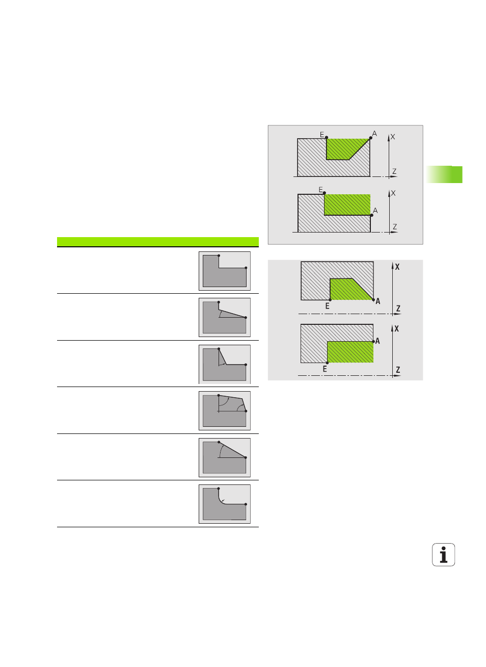
Tool position
It is important that you observe the tool positions (starting point X, Z)
before executing any of the turning cycles in expanded mode. The
rules also apply for all cutting and infeed directions as well as for
roughing and finishing (see examples of linear cycles).
The starting point must not be located in the shaded area.
The area to be machined starts at the starting point X, Z, if the
tool is positioned before the contour area. The control will otherwise
only machine the contour area defined.
If the starting point X, Z for internal machining is located above
the turning center, only the contour area defined will be machined.
(A = contour starting point X1, Z1; E = contour end point X2, Z2)
Contour elements
Contour elements in turning cycles
Basic mode
Machining a rectangular area
Expanded mode
Oblique cut at contour start
Expanded mode
Oblique cut at contour end
Expanded mode
Oblique cuts at contour start and end with
angles > 45°
Expanded mode
One
oblique cut (by entering the starting point
of contour, end point of contour and starting
angle)
Expanded mode
Rounding