4 turning cycles, 4 tu rn ing cy cles 4.4 turning cycles – HEIDENHAIN SW 68894x-02 User Manual
Page 146
146
Teach-in mode
4.4
Tu
rn
ing
cy
cles
4.4 Turning cycles
Cutting and infeed directions for turning cycles
The CNC PILOT automatically determines the cutting and infeed
directions from the cycle parameters.
Basic mode:
The parameters for starting point X, Z (Manual mode:
current tool position) and contour starting point X1 / contour end
point Z2 determine these directions.
Expanded mode:
The parameters for contour starting point X1, Z1
and contour end point X2, Z2 determine these directions.
ICP cycles:
The parameters for contour starting point X, Z (Manual
mode: current tool position) and starting point of the ICP contour
determine these directions.
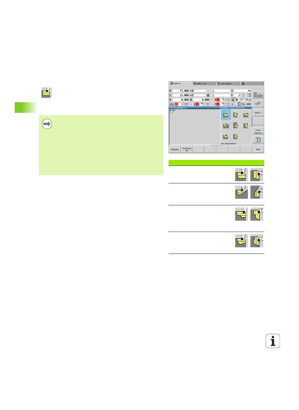
Turning cycles
Symbol
Turning, longitudinal/transverse
Roughing and finishing cycle for
simple contours
Plunge-cutting, longitudinal/
transverse
Roughing and finishing cycle for
simple plunge-cut contours
ICP contour-parallel,
longitudinal/transverse
Roughing and finishing cycle for
any type of contour (cutting paths
parallel to finished part)
ICP turning, longitudinal/
transverse
Roughing and finishing cycle for
any type of contour
Turning cycles rough and finish simple contours in basic
mode
and complex contours in expanded mode.
With ICP cutting cycles, you can machine contours
defined with ICP. See "ICP contours" on page 360.
Proportioning of cuts:
The CNC PILOT calculates an
infeed that is <=infeed depth P. An "abrasive cut" is
avoided.
Oversizes:
Oversizes are considered in "expanded"
mode.
Cutter radius compensation:
Active
Safety clearance
after each step:
Basic mode: 1 mm
Expanded mode: The safety clearance is set
separately for internal and external machining (see