A 29 b – Grass Valley Concerto Routing Matrix v.1.8.1 User Manual
Page 95
Concerto — Installation and Service Manual
95
Cabling
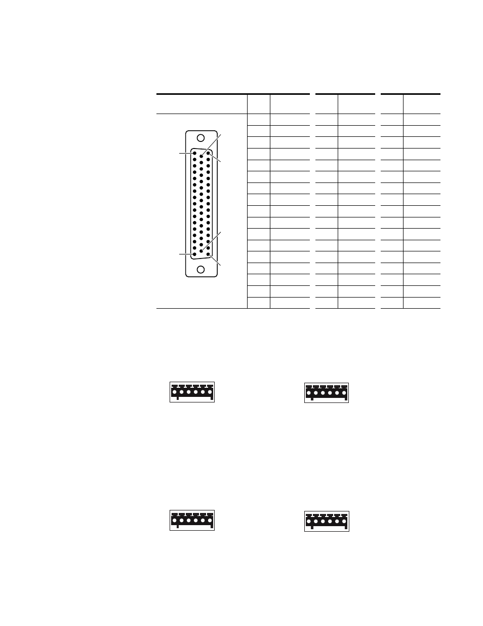
contains pinout information for the Input and Output connectors
on the Balanced 50 Pin D Digital Audio (AES) Backplane.
shows the pinouts for Inputs and Outputs using terminal block
connectors on the Analog Audio and AES Audio backplanes.
Figure 46. Terminal Block Inputs and Outputs Pinouts
shows the pinouts for Monitoring using terminal block connec-
tors on the Analog Audio and AES Audio backplanes.
Figure 47. Terminal Block Monitor Pinouts
Table 42. AES Audio Input/Output 50 Pin D Connector Pinouts
Input/Output D Connector
AES Audio
Pin
Function
Pin
Function
Pin
Function
1
Ground
18
1-
34
1+
2
2+
19
2-
35
Ground
3
Ground
20
3-
36
3+
4
4+
21
4-
37
Ground
5
Ground
22
5-
38
5+
6
6+
23
6-
39
Ground
7
Ground
24
7-
40
7+
8
8+
25
8-
41
Ground
9
Ground
26
9-
42
9+
10
10+
27
10-
43
Ground
11
Ground
28
11-
44
11+
12
12+
29
12-
45
Ground
13
Ground
30
13-
46
13+
14
14+
31
14-
47
Ground
15
Ground
32
15-
48
15+
16
16+
33
16-
49
Ground
17
-
-
-
50
-
50 Pin D Female
1
17
33
50
18
34
Use 110 Ohm Shielded Twisted
Pair Cable
A 29 B
A+, A-, GND, B+, B-, GND
29 30
29+, 29-, GND, 30+, 30-, GND
Analog Audio
Digital Audio
A B
A+, A-, GND, B+, B-, GND
IN OUT
IN+, IN-, GND, OUT+, OUT-, GND
Analog Audio
Digital Audio