128x128, Position – Grass Valley Concerto Routing Matrix v.1.8.1 User Manual
Page 44
44
Concerto — Installation and Service Manual
Section 1 — System Description
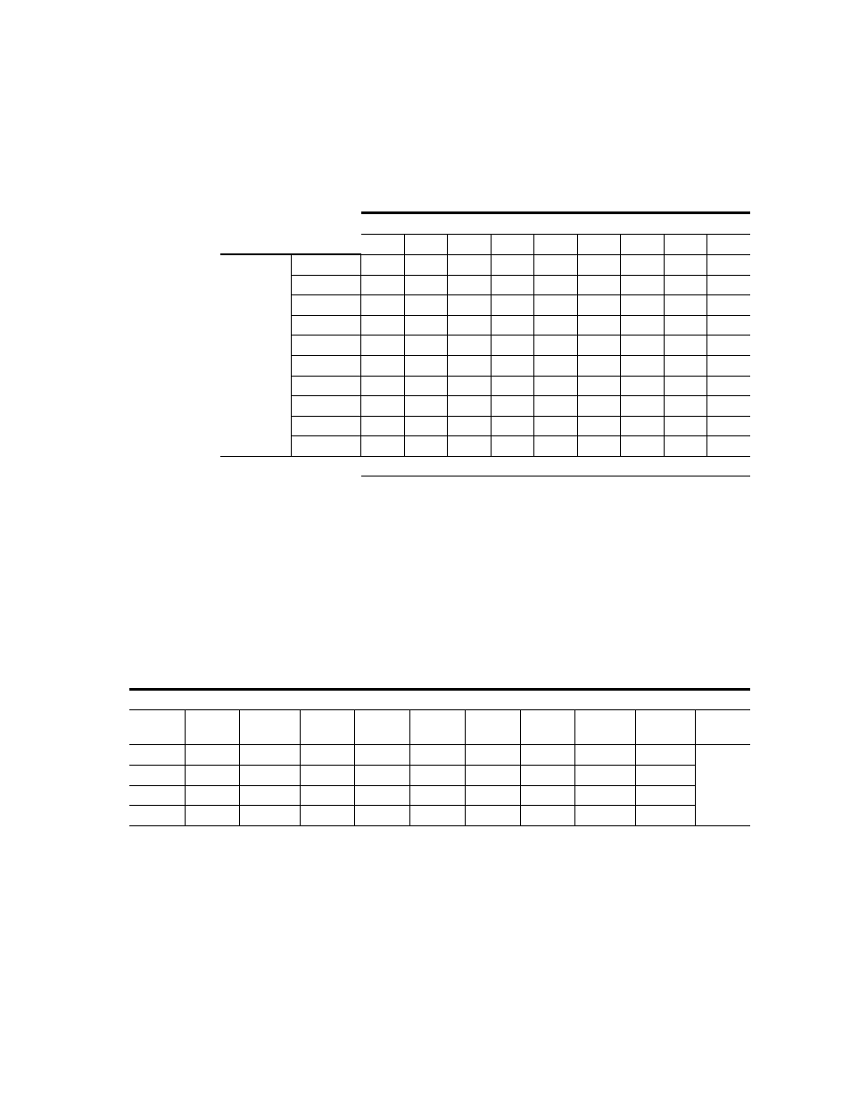
shows the Jupiter interface settings. Options 4 and 9 show settings
for Port modules, and Option 7 shows Time Code. The numbers shown for
the DIP switch banks indicate which of the eight switches should be set in
the
On
position.
128x128
and
show optimum module placement options for cre-
ating a single four module 128x128 matrix. There are three variations
shown (options 5 to 7) for a 128x128 matrix using mixed audio. In
the Analog to Digital and Digital to Analog converters are shown in the
mixed audio matrices. Additional combinations can be created using either
mixed audio, mixed video, or mixed data modules.
Table 14. Rotary and DIP Switch Settings for Jupiter Interface
Jupiter Settings for Options from
1
2
3
4
5
6
7
8
9
Switches
Rotary S12
3
3
3
3
3
3
3
3
3
Rotary S13
0
1
1
5
1
1
5
4
8
A_LEVEL
1
1
1
1
1, 2, 3
1, 2, 3
1, 2, 3
2
2
A_OPTIONS
-
-
-
-
-
-
-
-
-
B_LEVEL
1
1
1
1
1, 2, 3
1, 2, 3
1, 2, 3
2
2
B_OPTIONS
-
-
-
-
-
-
-
-
-
C_LEVEL
1
1
1
1
1, 2, 3
1, 2, 3
1, 2, 3
2
2
C_OPTIONS
-
-
-
-
-
-
-
-
-
D_LEVEL
1, 2, 3
2
6
5
2
6
1, 2
6
5
D_OPTIONS
-
-
-
-
-
-
1
-
-
DIP Switches set to ON Position
Table 15. Examples of Optimum Matrix Configurations (128x128)
One 128x128 Matrix
Slot
Position
Option 1
Modules
Option 2
a
Modules
a
For this option 1 or 2 HD or 3Gb/s video modules can be used with SD video modules to create a 128x128 Digital Video matrix.
Option 3
Modules
Option 4
Modules
Option 5
Modules
Option 6
Modules
Option 7
Modules
Option 8
b
Modules
b
All modules are Time Code.
Option 9
c
Modules
c
All modules are Port
Matrix
Size
1
AV
DV
AA
DA
AA
AA
AA
TCP
TCP
128x128
2
AV
DV
AA
DA
AA
AA
DA
TCP
TCP
3
AV
DV
AA
DA
AA
DA
DA
TCP
TCP
4
AV
DV
AA
DA
DA
DA
DA
TCP
TCP