Module configuration – Grass Valley Concerto Routing Matrix v.1.8.1 User Manual
Page 34
34
Concerto — Installation and Service Manual
Section 1 — System Description
Module Configuration
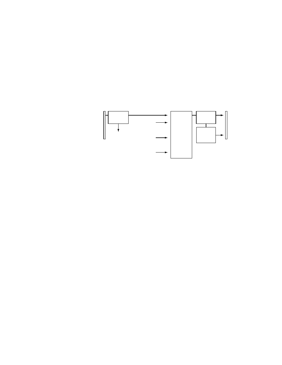
Each module receives 32 inputs from the backplane associated with the slot
position of the module. Each module delivers 32 outputs to the backplane
associated with the slot position of the module. In
, the module in
slot position 1 (top position) is receiving Inputs 1-32 from the backplane in
slot position 1. Because
shows a 128x128 matrix, Inputs 33-128 are
available to the module via the Interconnect module. The module can now
deliver any of the Sources connected to Inputs 1-128 to the Output connec-
tors 1-32 on the backplane in slot position 1.
Figure 2. Block Diagram for Module in Slot 1 (Top) in 128x128 Matrix
The Analog Audio module has dual Inputs and Outputs to accommodate
the Left and Right channels. These dual connections are labeled on the
backplane using a 1A/1B format. The default is to software configure the
1A (Left) and 1B (Right) channels as a stereo signal. AES Audio has single
Inputs and Outputs where the default is to software configure each con-
nector as a stereo signal.
The stereo channels can be configured to switch separately as mono signals.
The smallest mono matrix is a single module of 64x64 and the largest is
512x512 using two Concerto frames.
The module receives 64 inputs from the backplane associated with the slot
position of the module. Each module delivers 64 outputs to the backplane
associated with the slot position of the module. In
, the module in
slot position 1 is receiving Inputs 1A/1B-32A/32B from the backplane in
slot position 1.
shows a 256x256 matrix where Inputs 33A/33B-
128A/128B are available to the module via the Interconnect module. The
module can now deliver any of the Sources connected to Inputs 1A/1B-
128A/128B to the Output connectors 1A/1B-32A/32B on the backplane in
slot position 1.
32 Inputs
(1-32)
from Slot 1
backplane
Input (1-32)
Distribution
to Slots
2, 3, & 4
32 Inputs
(33-64)
from Matrix 2
32 Inputs
(97-128)
from Matrix 4
32 Inputs
(65-96)
from Matrix 3
32 Outputs
(1-32)
to Slot 1
backplane
128x32
Crosspoint
Matrix
32x1
Monitor
Crosspoint
Input
Equalization
Output
Reclocking
8138_00_62r0