Jupiter only variation, Off for sync 1, on for sync 2, Off for reclocking, on for forced bypass – Grass Valley Concerto Routing Matrix v.1.8.1 User Manual
Page 63
Concerto — Installation and Service Manual
63
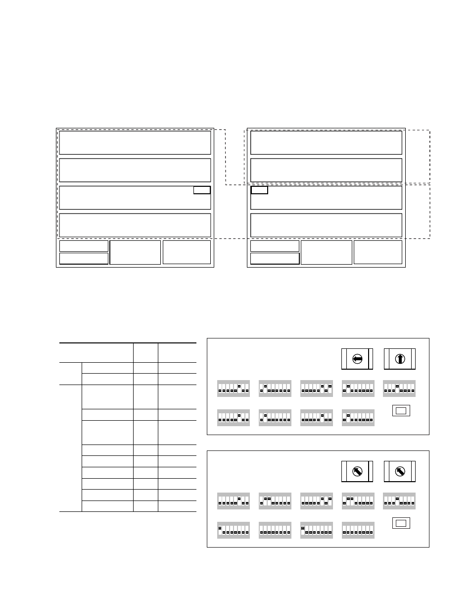
TDM Expansion
Jupiter Only Variation
shows the configuration of the two frames with a TDM sub-
module attached to the Audio modules in slot 3 of each frame. Two Video
modules are in slots 1 and 2 of the expansion frame.
Figure 24. 192x192 Audio and 64x64 Video
shows the Rotary and DIP switch settings on the CRS-MC-C2
Controller module for this configuration.
Figure 25. Switch Settings for 192x192 Audio and 64x64 Video
Power
Supply 2
Controller 1
Controller 2
Power
Supply 1
Input 161-192
Xpt (In=129-192, Out=161-192)
Output 161-192
Input 129-160
Xpt (In=129-192, Out=129-160)
Output 129-160
Input 33-64
Xpt (In=1-64, Out=33-64)
Output 33-64
8138_00_117
Power
Supply 2
Controller 1
Controller 2
Power
Supply 1
Input 97-128
Xpt (In=1-128, Out=97-128)
Output 97-128
Input 65-96
Xpt (In=1-128, Out=65-96)
Output 65-96
Input 33-64
Xpt (In=1-128, Out=33-64)
Output 33-64
Input 1-32
Xpt (In=1-128, Out=1-32)
Output 1-32
192x192
Matrix
64x64
Matrix
Input 1-32
Xpt (In=1-64, Out=1-32)
Output 1-32
TDM
TDM
1
8
7
6
5
4
3
2
ON
1
8
7
6
5
4
3
2
ON
1
8
7
6
5
4
3
2
ON
1
8
7
6
5
4
3
2
ON
1
8
7
6
5
4
3
2
ON
1
8
7
6
5
4
3
2
ON
1
8
7
6
5
4
3
2
ON
1
8
7
6
5
4
3
2
ON
1
8
7
6
5
4
3
2
ON
CLEAR MEM
A_LEVEL
B_LEVEL
A_OPTIONS
C_LEVEL
D_LEVEL
B_OPTIONS
C_OPTIONS
D_OPTIONS
MODE/IN
SEL
S11
S12
S13
A
B
C
D
E
F
G
H
A
B
C
D
E
F
G
H
A
B
C
D
E
F
G
H
A
B
C
D
E
F
G
H
M A T R I X MAP
C O N F I G
8138_04_133r0
4 5
6
7
8
9
A
B
C
D
E
F
0
1
2
3
4 5
6
7
8
9
A
B
C
D
E
F
0
1
2
3
1
8
7
6
5
4
3
2
ON
1
8
7
6
5
4
3
2
ON
1
8
7
6
5
4
3
2
ON
1
8
7
6
5
4
3
2
ON
1
8
7
6
5
4
3
2
ON
1
8
7
6
5
4
3
2
ON
1
8
7
6
5
4
3
2
ON
1
8
7
6
5
4
3
2
ON
1
8
7
6
5
4
3
2
ON
CLEAR MEM
A_LEVEL
B_LEVEL
A_OPTIONS
C_LEVEL
D_LEVEL
B_OPTIONS
C_OPTIONS
D_OPTIONS
MODE/IN
SEL
S11
S12
S13
A
B
C
D
E
F
G
H
A
B
C
D
E
F
G
H
A
B
C
D
E
F
G
H
A
B
C
D
E
F
G
H
M A T R I X MAP
C O N F I G
4 5
6
7
8
9
A
B
C
D
E
F
0
1
2
3
4 5
6
7
8
9
A
B
C
D
E
F
0
1
2
3
Expansion Frame
Base Frame
Switch
Base
Frame
Expansion
Frame
Rotary
S12 CONFIG
0
2
S13 MATRIX Map
4
2
DIP
Switch
Banks
A_LEVEL
6
1 = Analog
1, 2, 3 = SD
1, 4 = HD
A_OPTIONS
2
1-4
a
, 5-8
b
a
Off for Sync 1, On for Sync 2
b
Off for Reclocking, On for Forced Bypass
B_LEVEL
6
1 = Analog
1, 2, 3 = SD
1, 4 = HD
B_OPTIONS
2
1-4
, 5-8
C_LEVEL
6
6
C_OPTIONS
2
2, 3
D_LEVEL
6, 8
6, 8
D_OPTIONS
2
2, 3
S11 MODE IN SEL
4
4