Audio monitoring, Figure 52, Bnc connector on the backplane in slot 2 to the – Grass Valley Concerto Routing Matrix v.1.8.1 User Manual
Page 101: Bnc connector on the backplane in slot 3 to the, Con- nector and a bnc, Connector and a bnc, Mon in, Mon out, Monitor in, Monitor out
Concerto — Installation and Service Manual
101
Cabling
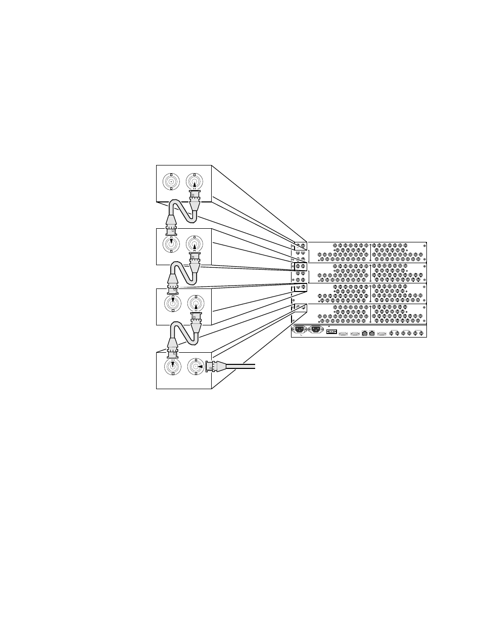
to the
Mon In
BNC connector on the backplane in slot 2. Then a cable is
looped from the
Mon Out
BNC connector on the backplane in slot 2 to the
Mon
In
BNC connector on the backplane in slot 3. And a third cable is looped
from the
Mon Out
BNC connector on the backplane in slot 3 to the
Mon In
BNC
connector on the backplane in slot 4. A cable is then attached to the
Mon Out
BNC connector on backplane 4 and a monitoring device. For more informa-
tion on configured matrix sizes a see
Digital Video Monitor Configuration on
Figure 52. Digital Video External Cabling
Audio Monitoring
Analog and AES Digital modules can be combined in the same configured
matrix, and they use internal bussing to support monitor functions, so all
outputs in the matrix are available.
Monitor In
connections are not used. One
Destination signal is available to all of the
Monitor Out
connectors in the con-
figured matrix. All the backplanes have at least one
Monitor Out
connector.
Two of the AES Audio backplanes have two
Monitor
Out
connectors. On the
AES Terminal Block backplane there is a terminal block
Monitor Out
con-
nector and a BNC
Monitor Out
connector and on the AES 50 pin D backplane
there is a 9 pin D
Monitor Out
connector and a BNC
Monitor Out
connector. See
for the 9 pin D connector pinouts used on the 50 pin D
backplanes. See
for the terminal block connector
pinouts used on the terminal block backplanes. For more information on
Concerto
EXT COM
2
EXT COM
1
E-NET
2
E-NET
1
AES REF
VID-REF 2
VID-REF 1
25
21
17
13
9
5
1
22
18
14
10
6
2
26
23
19
15
11
7
3
28
27
30
29
31
32
24
20
16
12
8
4
31
27
23
19
15
11
7
28
24
20
16
12
8
32
29
25
21
17
13
9
30
26
22
18
14
10
5
6
3
4
1
2
INPUTS
OUTPUTS
EXP
IN
EXP
OUT
AUDIO/DATA
TDM
MON IN
MON OUT
1
2
1
2
25
21
17
13
9
5
1
22
18
14
10
6
2
26
23
19
15
11
7
3
28
27
30
29
31
32
24
20
16
12
8
4
31
27
23
19
15
11
7
28
24
20
16
12
8
32
29
25
21
17
13
9
30
26
22
18
14
10
5
6
3
4
1
2
INPUTS
OUTPUTS
EXP
IN
EXP
OUT
AUDIO/DATA
TDM
MON IN
MON OUT
1
2
1
2
400W; 11.1A
36-60V
+
-
AC PWR 1
AC PWR 2
500W; 5A
50/60Hz
100-240V
ALARM
8138_04_155r0
25
21
17
13
9
5
1
22
18
14
10
6
2
26
23
19
15
11
7
3
28
27
30
29
31
32
24
20
16
12
8
4
31
27
23
19
15
11
7
28
24
20
16
12
8
32
29
25
21
17
13
9
30
26
22
18
14
10
5
6
3
4
1
2
INPUTS
OUTPUTS
MON IN
MON OUT
H D B A C K P L A N E
25
21
17
13
9
5
1
22
18
14
10
6
2
26
23
19
15
11
7
3
28
27
30
29
31
32
24
20
16
12
8
4
31
27
23
19
15
11
7
28
24
20
16
12
8
32
29
25
21
17
13
9
30
26
22
18
14
10
5
6
3
4
1
2
INPUTS
OUTPUTS
MON IN
MON OUT
H D B A C K P L A N E
MON IN
MON OUT
MON IN
MON OUT
MON IN
MON OUT
MON IN
MON OUT
Slot 1, Outputs 1-32,
Cable Mon Out to Mon In
in Slot 2
Slot 2, Outputs 1-64,
Cable Mon Out to Mon In
in Slot 3
Slot 3, Outputs 1-96,
Cable Mon Out to Mon In
in Slot 4
Slot 4, Outputs 1-128
Slot 4, Outputs 1-128,
Cable Mon Out
to Monitoring Device