Position – Grass Valley Concerto Routing Matrix v.1.8.1 User Manual
Page 46
46
Concerto — Installation and Service Manual
Section 1 — System Description
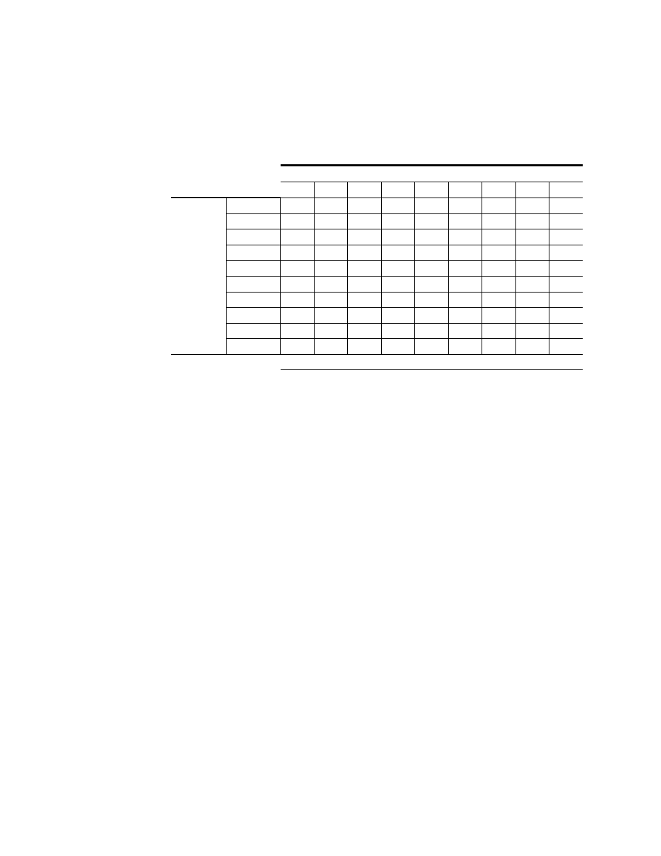
shows the Jupiter interface settings. Option 8 shows settings for
Time Code modules, and Option 9 shows Port. The numbers shown for the
DIP switch banks indicate which of the eight switches should be set in the
On
position.
Table 16. Rotary and DIP Switch Settings for Jupiter Interface
Jupiter Settings for Options from
1
2
3
4
5
a
a
Mixed Audio modules use AES Digital Audio as level.
6
7
8
b
b
All modules Time Code.
9
c
c
All modules Port.
Switches
Rotary S12
0
0
0
0
0
0
0
0
0
Rotary S13
0
0
4
4
4
4
4
E
E
A_LEVEL
1
1, 2, 3
2
6
6
6
6
1, 2
5
A_OPTIONS
-
-
-
-
-
-
-
1
-
B_LEVEL
1
1, 2, 3
2
6
6
6
6
1, 2
5
B_OPTIONS
-
-
-
-
-
-
-
1
-
C_LEVEL
1
1, 2, 3
2
6
6
6
6
1, 2
5
C_OPTIONS
-
-
-
-
-
-
-
1
-
D_LEVEL
1
1, 2, 3
2
6
6
6
6
1, 2
5
D_OPTIONS
-
-
-
-
-
-
-
1
-
DIP Switches set to ON Position