Grass Valley Concerto Routing Matrix v.1.8.1 User Manual
Page 130
130
Concerto — Installation and Service Manual
Section 3 — Control System Configuration
3.
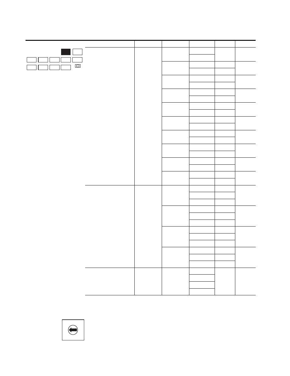
Set Rotary Switch S13 for format of each module to slot.
4 5
6
7
8
9
A
B
C
D
E
F
0
1
2
3
identifies the setting for Rotary Switch S13. This setting iden-
tifies the format of the module in each of the four slots. If you have
Two levels
2
2
32x32
Any
7
32x32
3
32x32
1
6
64x64
2 & 3
3
32x32
1
4
64x64
3 & 4
3
32x32
2
4
64x64
3 & 4
3
64x64
1 & 2
5
32x32
3
3
64x64
1 & 2
5
32x32
4
3
64x64
2 & 3
6
32x32
4
4
64x64
1 & 2
2
64x64
3 & 4
4
32x32
1
1
96x96
2, 3, 4
4
96x96
1, 2, 3
3
32x32
4
Three levels
3
3
32x32
Any
7
32x32
Any
32x32
Any
4
32x32
1
4
32x32
2
64x64
3 & 4
4
32x32
1
6
64x64
2 & 3
32x32
4
4
64x64
1 & 2
5
32x32
3
32x32
4
Four levels
4
4
32x32
Any
7
32x32
32x32
32x32
a
All Rotary Switch positions that are not listed in this column are undefined.
Table 47. S12 Rotary Switch Settings for Matrix Configuration - (continued)
Levels
# of Matrices
# of Modules
Matrix Size
Slot #
Setting
a
CLEAR MEM
S2
S5
S11
S10
S13
S12
S4
S3
S9
S8
S7
A_LEVEL
B_LEVEL
A_OPTION
S
C_LEVEL
D_LEVEL
B_OPTION
S
C_OPTION
S
D_OPTION
S
MODE/IN
S
EL
S
11
S
12
S
13
A
B
C
D
E
F
G
H
A
B
C
D
E
F
G
H
A
B
C
D
E
F
G
H
A
B
C
D
E
F
G
H
M A T R I X MAP
C O N F I G