Figure 5, Position – Grass Valley Concerto Routing Matrix v.1.8.1 User Manual
Page 42
42
Concerto — Installation and Service Manual
Section 1 — System Description
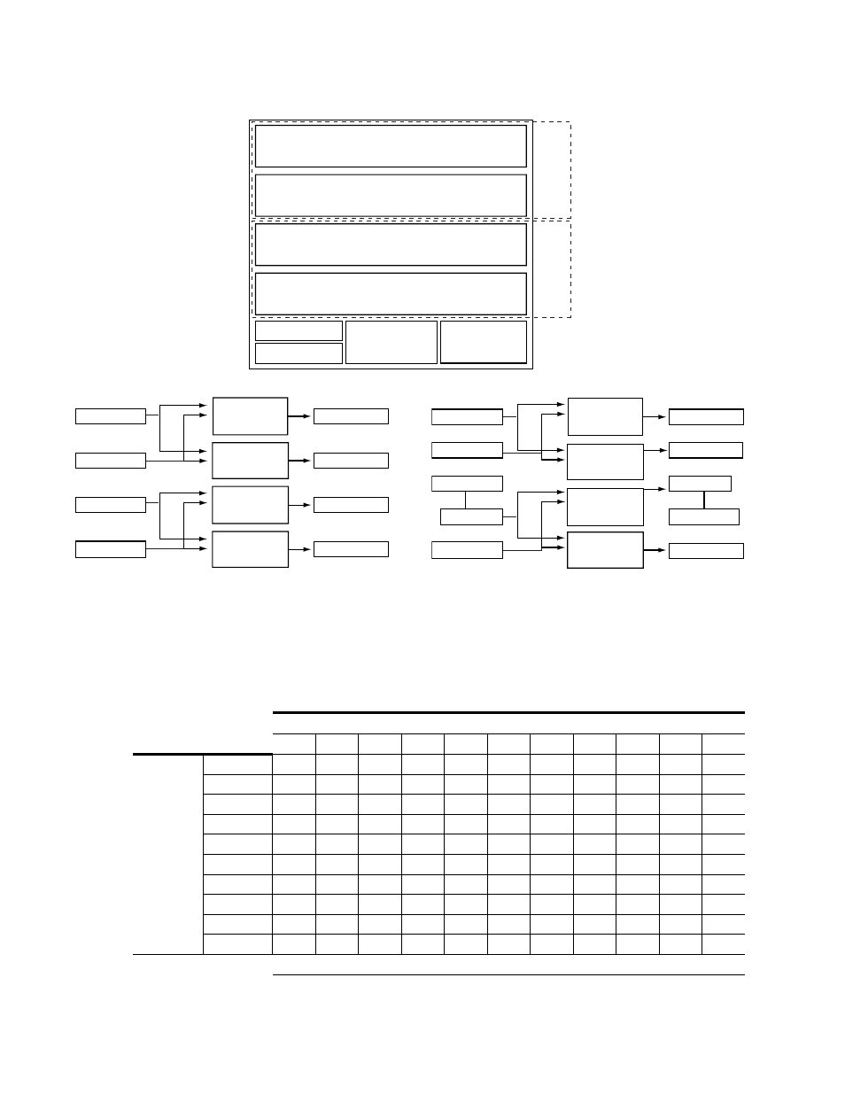
Figure 5. Two 64x64 Module Configuration and Signal Flow
shows the Jupiter interface settings. Options 4, 10, and 11 show set-
tings for Port modules, and Option 8 shows the settings for Time Code. The
numbers shown for the DIP switch banks indicate which of the eight
switches should be set in the
On
position.
Table 12. Rotary and DIP Switch Settings for Jupiter Interface
Jupiter Settings for Options from
1
2
3
4
5
6
7
8
9
10
11
Switches
Rotary S12
2
2
2
2
2
2
2
2
2
2
2
Rotary S13
0
2
2
6
2
2
2
6
4
9
9
A_LEVEL
1
1
1
1
1
1, 2, 3
1, 2, 3
1, 2, 3
2
2
6
A_OPTIONS
-
-
-
-
-
-
-
-
-
-
-
B_LEVEL
1
1
1
1
1
1, 2, 3
1, 2, 3
1, 2, 3
2
2
6
B_OPTIONS
-
-
-
-
-
-
-
-
-
-
-
C_LEVEL
1, 2, 3
2
6
5
6
2
6
1, 2
6
5
5
C_OPTIONS
-
-
-
-
-
-
-
1
-
-
-
D_LEVEL
1, 2, 3
2
6
5
6
2
6
1, 2
6
5
5
D_OPTIONS
-
-
-
-
-
-
-
1
-
-
-
DIP Switches set to ON Position
8138_00_49r0
Inputs 1-32
Outputs 1-32
Xpt (In=1-64,
Out=1-32)
Inputs 33-64
Inputs 33-64
Outputs 33-64
Xpt (In=1-64,
Out=33-64)
Xpt (In=1-64,
Out=1-32)
Xpt (In=1-64,
Out=33-64)
Inputs 1-32
A to D Conv.
D to A Conv.
Outputs 1-32
Outputs 33-64
Signal Flow for Option 5
8138_00_33r0
64x64
Matrix
64x64
Matrix
Power
Supply 2
Controller 1
Controller 2
Power
Supply 1
Input 33-64
Xpt (In=1-64, Out=33-64)
Output 33-64
Input 1-32
Xpt (In=1-64, Out=1-32)
Output 1-32
Input 33-64
Xpt (In=1-64, Out=33-64)
Output 33-64
Input 1-32
Xpt (In=1-64, Out=1-32)
Output 1-32
8138_00_44r0
Inputs 1-32
Outputs 1-32
Xpt (In=1-64,
Out=1-32)
Inputs 1-32
Outputs 1-32
Xpt (In=1-64,
Out=1-32)
Inputs 33-64
Outputs 33-64
Xpt (In=1-64,
Out=33-64)
Xpt (In=1-64,
Out=33-64)
Inputs 33-64
Outputs 33-64
Signal Flow for Options 1 to 4, and 6 to 11