32x32 / 64x64 / 32x32, Table 20, Position – Grass Valley Concerto Routing Matrix v.1.8.1 User Manual
Page 50
50
Concerto — Installation and Service Manual
Section 1 — System Description
Code. The numbers shown for the DIP switch banks indicate which of the
eight switches should be set in the
On
position.
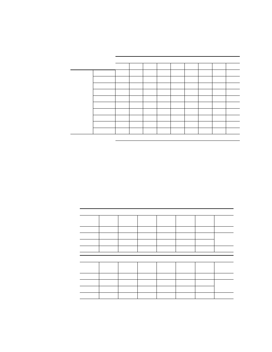
32x32 / 64x64 / 32x32
and
show optimum module placement options for cre-
ating a single modules 32x32 matrix, a two module 64x64 matrix and a
second single module 32x32 matrix. 64x32 Video modules cannot be used
in slots 2 and 3 to create a 64x64 matrix. Use 128x32 Video modules for these
configurations. Additional combinations can be created using either mixed
audio, mixed video, or mixed data modules.
Table 20. Rotary and DIP Switch Settings for Jupiter Interface
Jupiter Settings for Options from
1
2
3
4
5
6
7
8
9
Switches
Rotary S12
5
5
5
5
5
5
5
5
5
Rotary S13
1
1
5
2
B
2
B
B
8
A_LEVEL
1
1
1
1
1
1, 2, 3
1, 2, 3
1, 2, 3
2
A_OPTIONS
-
-
-
-
-
-
-
-
-
B_LEVEL
1
1
1
1
1
1, 2, 3
1, 2, 3
1, 2, 3
2
B_OPTIONS
-
-
-
-
-
-
-
-
-
C_LEVEL
1, 2, 3
1, 2, 3
1, 2, 3
2
2
2
2
6
6
C_OPTIONS
-
-
-
-
-
-
-
-
-
D_LEVEL
2
6
5
6
1, 2
6
5
5
1, 2
D_OPTIONS
-
-
-
-
1
-
-
-
1
DIP Switches set to ON Position
Table 21. Examples of Optimum Matrix Configurations (32x32,64x64, and 32x32)
One 32x32 Matrix, One 64x64 Matrix, & One 32x32 Matrix Options 1 to 6
Slot
Position
Option 1
Modules
Option 2
Modules
Option 3
Modules
Option 4
Modules
Option 5
Modules
Option 6
Modules
Matrix
Size
1
AV
AV
AV
AV
AV
AV
32x32
2
DV
DV
DV
AA
AA
AA
64x64
3
DV
DV
DV
AA
AA
DA
4
AA
DA
TCP
DA
TCP
TCP
32x32
One 32x32 Matrix, One 64x64 Matrix, & One 32x32 Matrix Options 7 to 12
Slot
Position
Option 7
Modules
Option8
Modules
Option 9
Modules
Option 10
Modules
Option 11
Modules
Option 12
Modules
Matrix
Size
1
AV
DV
DV
DV
DV
AA
32x32
2
DA
AA
AA
AA
DA
DA
64x64
3
DA
AA
AA
DA
DA
DA
4
TCP
DA
TCP
TCP
TCP
TCP
32x32