Remove one old controller module, Insert and seat one new controller module. the, Power ok) and – Grass Valley Concerto Routing Matrix v.1.8.1 User Manual
Page 150: Led to turn on. continued commands prompt the, Led to flash, Remove the other old controller module, Insert and seat the other new controller. the, Led to turn on, Led to turn on. continued commands will prompt the, Pwr ok
150
Concerto — Installation and Service Manual
Section 5 — Maintenance and Troubleshooting
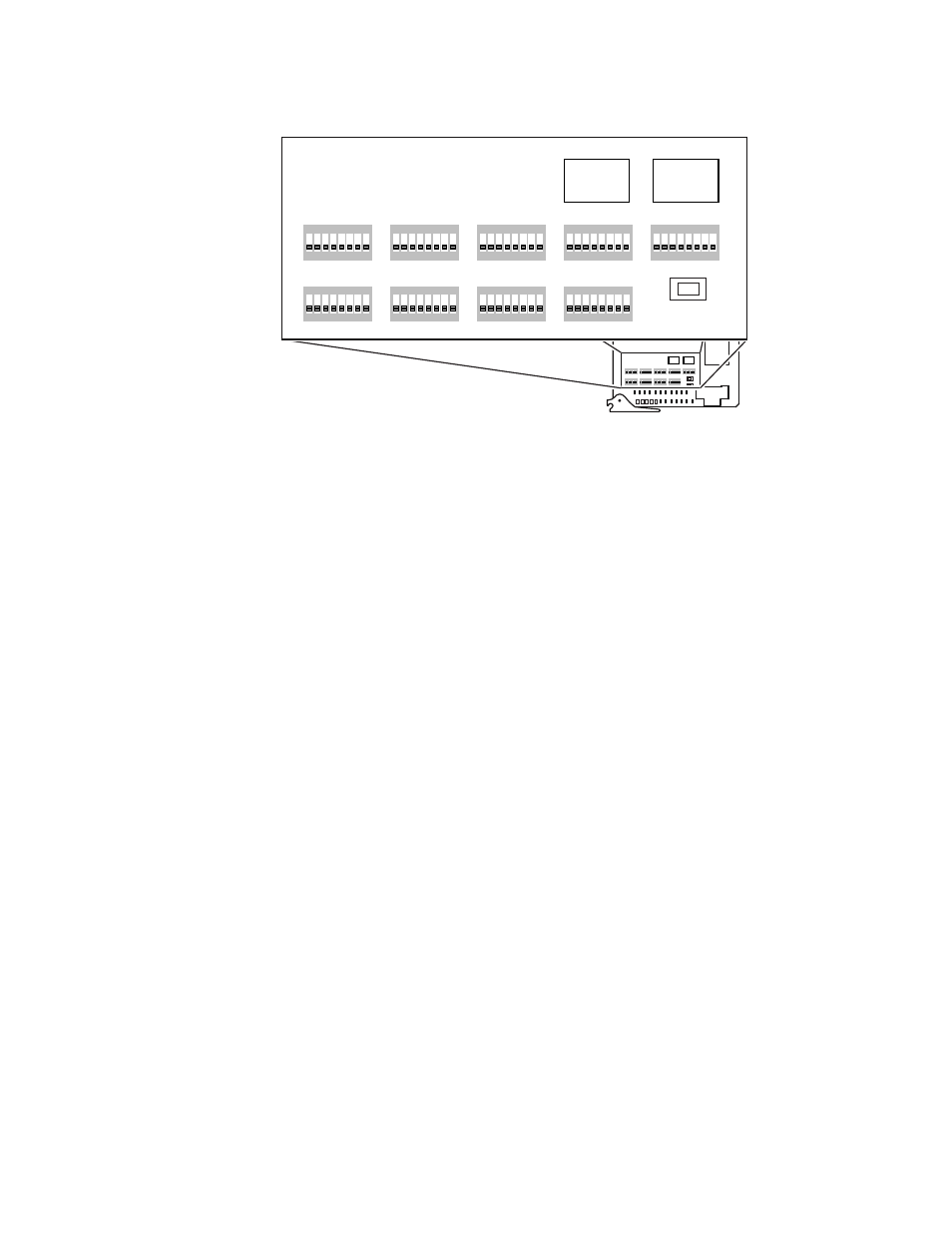
Figure 84. DIP Switches and Rotary Switches
3.
Remove one old Controller module.
4.
Insert and seat one new Controller module.
The
PWR OK
(power OK) and
DONE
LED will light signifying the new
module is up and ready to receive commands.
5.
Press the reset switch on the redundant old Controller, causing control
to be handed off to the newly inserted Controller.
The next command sent from the control system will cause the
ACT
LED
to turn on. Continued commands prompt the
ACT
LED to flash.
6.
Send and verify a switch command from the control system.
7.
Remove the other old Controller module.
8.
Insert and seat the other new Controller.
The
PWR OK
(power OK) and
DONE
LED will light signifying the new
module is up and ready to receive commands.
9.
The next command sent from the control system will cause the
ACT
LED
to turn on.
10.
Press reset on the Controller that is active to transfer control to the
second new Controller.
The next command sent from the control system will cause the
ACT
LED
to turn on. Continued commands will prompt the
ACT
LED to flash.
11.
Send and verify a switch command from the control system.
8138_04_150r0
1
8
7
6
5
4
3
2
ON
1
8
7
6
5
4
3
2
ON
1
8
7
6
5
4
3
2
ON
1
8
7
6
5
4
3
2
ON
1
8
7
6
5
4
3
2
ON
1
8
7
6
5
4
3
2
ON
1
8
7
6
5
4
3
2
ON
1
8
7
6
5
4
3
2
ON
1
8
7
6
5
4
3
2
ON
PWR
OK
DONE
ACT
GND
+5V
ERROR
TC2
PRES
BUSY
48K
PRES
LINK
SYNC
ERR
RECV
VI 2
PRES
XMIT
VI 1
PRES
CLEAR MEM
RESET
TX
RX
FAST
COL
TC1
PRES
+2.5V
+3.3V
A_LEVEL
B_LEVEL
A_OPTIONS
C_LEVEL
D_LEVEL
B_OPTIONS
C_OPTIONS
D_OPTIONS
MODE/IN
SEL
S11
S12
S13
A
B
C
D
E
F
G
H
A
B
C
D
E
F
G
H
A
B
C
D
E
F
G
H
A
B
C
D
E
F
G
H
M A T R I X MAP
C O N F I G
1
8
7
6
5
4
3
2
ON
1
8
7
6
5
4
3
2
ON
1
8
7
6
5
4
3
2
ON
1
8
7
6
5
4
3
2
ON
1
8
7
6
5
4
3
2
ON
1
8
7
6
5
4
3
2
ON
1
8
7
6
5
4
3
2
ON
1
8
7
6
5
4
3
2
ON
1
8
7
6
5
4
3
2
ON
CLEAR MEM
A_LEVEL
B_LEVEL
A_OPTIONS
C_LEVEL
D_LEVEL
B_OPTIONS
C_OPTIONS
D_OPTIONS
MODE/IN
SEL
S11
S12
S13
A
B
C
D
E
F
G
H
A
B
C
D
E
F
G
H
A
B
C
D
E
F
G
H
A
B
C
D
E
F
G
H
M A T R I X MAP
C O N F I G
Rotary
Switch
Rotary
Switch