Binary, Dip switch # position condition, 1on time code off port – Grass Valley Concerto Routing Matrix v.1.8.1 User Manual
Page 134: Switches 5 through 8 are undefined, Switches 2 through 8 are undefined
134
Concerto — Installation and Service Manual
Section 3 — Control System Configuration
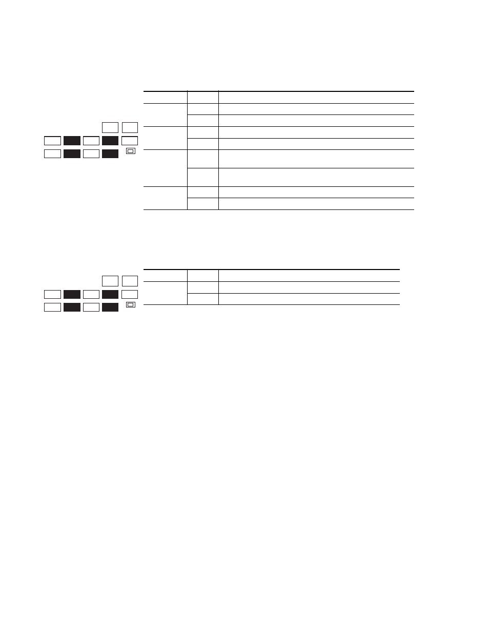
shows the option setting choices for Audio modules.
shows the option setting choices for Data modules.
7.
Complete the configuration on the Jupiter Control System.
On the Jupiter Control System configuration a Concerto matrix is con-
figured as a standard crosspoint bus control Routing switcher using the
Switcher Description, Input, and Output tables. On the Switcher
Description table, select
Binary
as the Driver type.
The location (output number) of the Concerto Monitor output in non-
expanded systems is the next output following the main matrix. For
example, for a 64 x 64 Routing switcher the Monitor output number
would be
65
. For expanded systems, the Monitor is the next output fol-
lowing the main matrix, assuming that the expansion is fully popu-
lated. This is because the Base matrix has no knowledge of the size of
the Expansion matrix, so it has to assume the maximum possible.
For more information on the Jupiter Control System configuration,
refer to the Jupiter Getting Started Guide (part # 040457070XX), and the
Jupiter Installation and Operating Manual (part # 0718261XX).
Table 52. Audio Option Settings for DIP Switch Banks S3, S5, S8, and S10
a
a
Switches 5 through 8 are undefined.
DIP Switch #
Position
Condition
1
ON
Mono (not supported)
OFF
Stereo (default)
2
ON
Expanded system - more than one Concerto frame
OFF
Not Expanded - one Concerto frame
3
ON
If Switch # 2 is On, module is in expansion frame (I/O 129-256)
If Switch # 2 is Off, this setting is invalid
OFF
If Switch # 2 is On, module is in base frame of expanded system (I/O 1-128)
If Switch # 2 is Off, single frame.
4
ON
24 bit processing
OFF
20 bit processing
Table 53. Data Options Settings for DIP Switch Banks S3, S5, S8, and S10
a
a
Switches 2 through 8 are undefined.
DIP Switch #
Position
Condition
1
ON
Time Code
OFF
Port
CLEAR MEM
S2
S5
S11
S10
S13
S12
S4
S3
S9
S8
S7
A_LEVEL
B_LEVEL
A_OPTION
S
C_LEVEL
D_LEVEL
B_OPTION
S
C_OPTION
S
D_OPTION
S
MODE/IN
S
EL
S
11
S
12
S
13
A
B
C
D
E
F
G
H
A
B
C
D
E
F
G
H
A
B
C
D
E
F
G
H
A
B
C
D
E
F
G
H
M A T R I X MAP
C O N F I G
CLEAR MEM
S2
S5
S11
S10
S13
S12
S4
S3
S9
S8
S7
A_LEVEL
B_LEVEL
A_OPTION
S
C_LEVEL
D_LEVEL
B_OPTION
S
C_OPTION
S
D_OPTION
S
MODE/IN
S
EL
S
11
S
12
S
13
A
B
C
D
E
F
G
H
A
B
C
D
E
F
G
H
A
B
C
D
E
F
G
H
A
B
C
D
E
F
G
H
M A T R I X MAP
C O N F I G