Optimum matrix configurations – Grass Valley Concerto Routing Matrix v.1.8.1 User Manual
Page 38
38
Concerto — Installation and Service Manual
Section 1 — System Description
Optimum Matrix Configurations
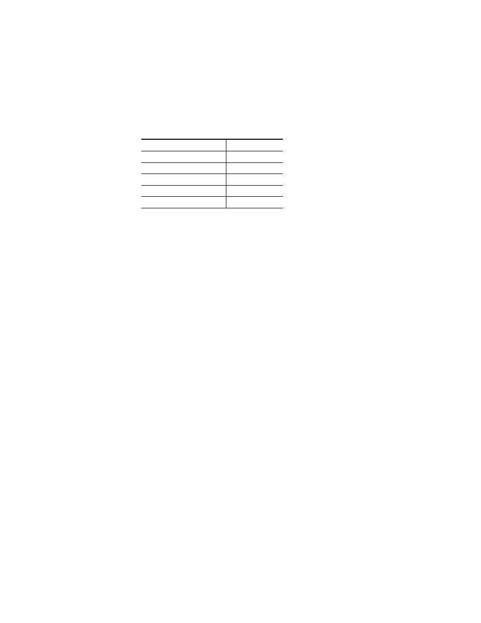
Optimum performance is achieved by positioning the modules in the
frame using the top to bottom priority shown in
Note
This hierarchy is required for interfacing to Jupiter Control Systems.
CAUTION The maximum number of HD modules that can be in a 7 RU Concerto frame
is three in which case the fourth slot has to remain empty. If two HD modules
are used then the other two slots can be loaded with any of the non HD mod-
ules.
Note
Because the 8 RU Concerto+ frame provides additional power and cooling
capacity when compared to the 7 RU frame, there are no restrictions on the
number of HD video modules in 8 RU frames.
The following are general guidelines:
•
Empty slots need to be identified for their future use, such as HD Video,
•
All modules that are in the same level must be next to each other in the
frame,
•
The preferred hierarchy between SD and HD Video modules in the
same frame is to place the SD modules before the HD modules. If you
have a frame with two SD modules and two HD modules, place the SD
modules in slots 1 (top) and 2, and the HD modules in slots 3 and 4, and
•
There is no preferred hierarchy between Time Code and Port modules
in the same frame.
Table 8. Top-to-bottom Module Positions
Module
Abbreviation
Analog Video
AV
Digital Video (SD, HD, or 3Gb/s)
DV
Analog Audio
AA
Digital Audio (AES)
DA
Data (Time Code or Port)
TCP