Expansion frame base frame, Off for sync 1, on for sync 2, Off for reclocking, on for forced bypass – Grass Valley Concerto Routing Matrix v.1.8.1 User Manual
Page 67
Concerto — Installation and Service Manual
67
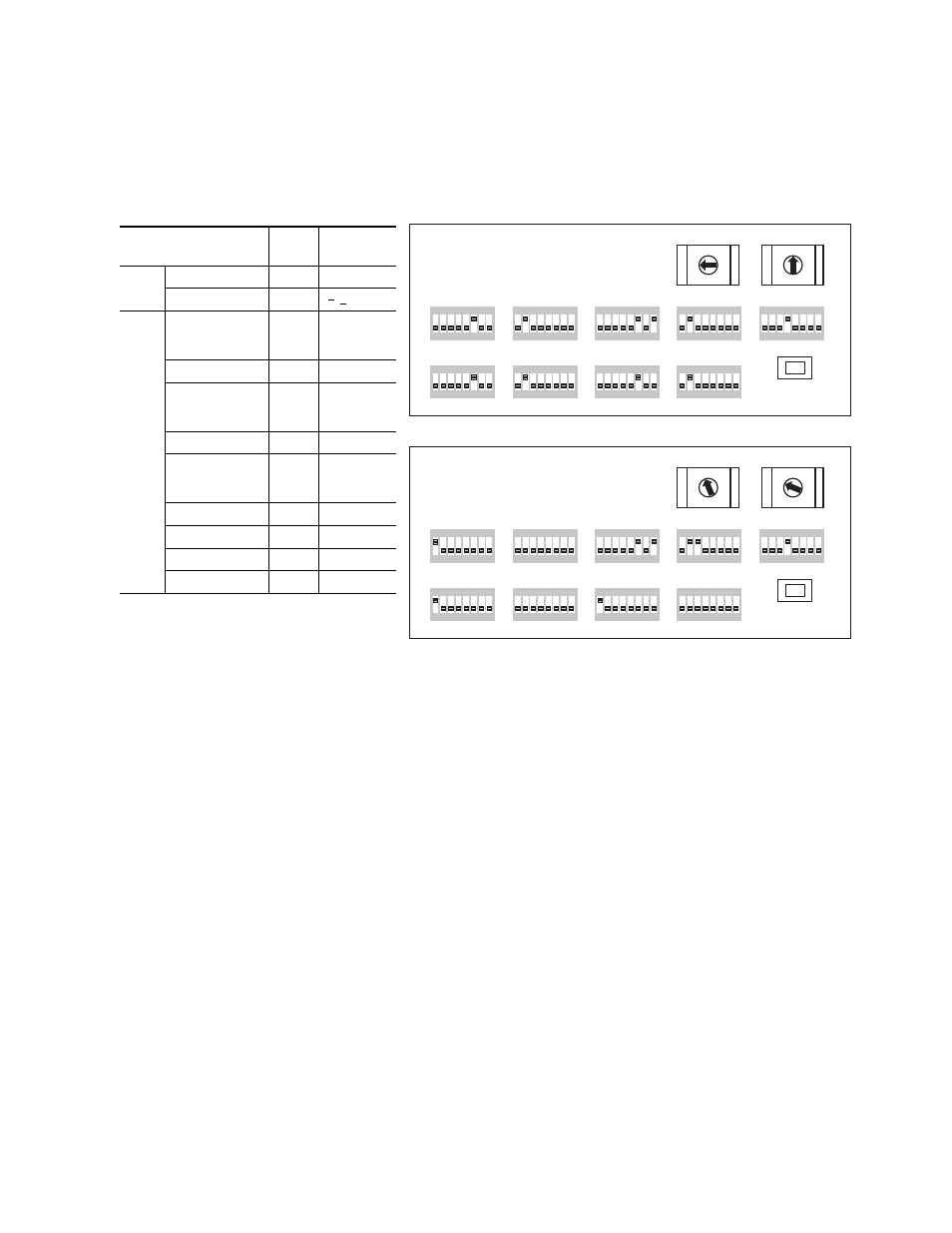
TDM Expansion
shows the Rotary and DIP switch settings on the CRS-MC-C2
Controller module for this configuration.
Figure 30. Switch Settings for 160x160 Audio and 96x96 Video
Switch
Base
Frame
Expansion
Frame
Rotary
S12 CONFIG
0
3
S13 MATRIX Map
4
[3] 1
DIP
Switch
Banks
A_LEVEL
6
1 = Analog
1, 2, 3 = SD
1, 4 = HD
A_OPTIONS
2
1-4
a
, 5-8
b
a
Off for Sync 1, On for Sync 2
b
Off for Reclocking, On for Forced Bypass
B_LEVEL
6
1 = Analog
1, 2, 3 = SD
1, 4 = HD
B_OPTIONS
2
1-4
, 5-8
C_LEVEL
6
1 = Analog
1, 2, 3 = SD
1, 4 = HD
C_OPTIONS
2
, 5-8
D_LEVEL
6, 8
6, 8
D_OPTIONS
2
2, 3
S11 MODE IN SEL
4
4
1
8
7
6
5
4
3
2
ON
1
8
7
6
5
4
3
2
ON
1
8
7
6
5
4
3
2
ON
1
8
7
6
5
4
3
2
ON
1
8
7
6
5
4
3
2
ON
1
8
7
6
5
4
3
2
ON
1
8
7
6
5
4
3
2
ON
1
8
7
6
5
4
3
2
ON
1
8
7
6
5
4
3
2
ON
CLEAR MEM
A_LEVEL
B_LEVEL
A_OPTIONS
C_LEVEL
D_LEVEL
B_OPTIONS
C_OPTIONS
D_OPTIONS
MODE/IN
SEL
S11
S12
S13
A
B
C
D
E
F
G
H
A
B
C
D
E
F
G
H
A
B
C
D
E
F
G
H
A
B
C
D
E
F
G
H
M A T R I X MAP
C O N F I G
8138_04_135r1
4 5
6
7
8
9
A
B
C
D
E
F
0
1
2
3
4 5
6
7
8
9
A
B
C
D
E
F
0
1
2
3
1
8
7
6
5
4
3
2
ON
1
8
7
6
5
4
3
2
ON
1
8
7
6
5
4
3
2
ON
1
8
7
6
5
4
3
2
ON
1
8
7
6
5
4
3
2
ON
1
8
7
6
5
4
3
2
ON
1
8
7
6
5
4
3
2
ON
1
8
7
6
5
4
3
2
ON
1
8
7
6
5
4
3
2
ON
CLEAR MEM
A_LEVEL
B_LEVEL
A_OPTIONS
C_LEVEL
D_LEVEL
B_OPTIONS
C_OPTIONS
D_OPTIONS
MODE/IN
SEL
S11
S12
S13
A
B
C
D
E
F
G
H
A
B
C
D
E
F
G
H
A
B
C
D
E
F
G
H
A
B
C
D
E
F
G
H
M A T R I X MAP
C O N F I G
4 5
6
7
8
9
A
B
C
D
E
F
0
1
2
3
4 5
6
7
8
9
A
B
C
D
E
F
0
1
2
3
Expansion Frame
Base Frame