Jupiter crosspoint bus controller configuration, Crosspoint bus controller settings, Through – Grass Valley Concerto Routing Matrix v.1.8.1 User Manual
Page 128
128
Concerto — Installation and Service Manual
Section 3 — Control System Configuration
Jupiter Crosspoint Bus Controller Configuration
If you are using a Jupiter Control System you will need to follow the
instructions for matrix configuration found in the Jupiter Installation and
Operating Manual. The Crosspoint Bus Controller (CRS-MC-C2) requires
specific settings. This section highlights those distinctions.
CAUTION If you are using a CRS-MC-C2 Controller module, the mode setting on DIP
Switch bank S11 must be set correctly before it will communicate the Cros-
spoint Bus. See
Control Mode/In Sel Setting on page 109
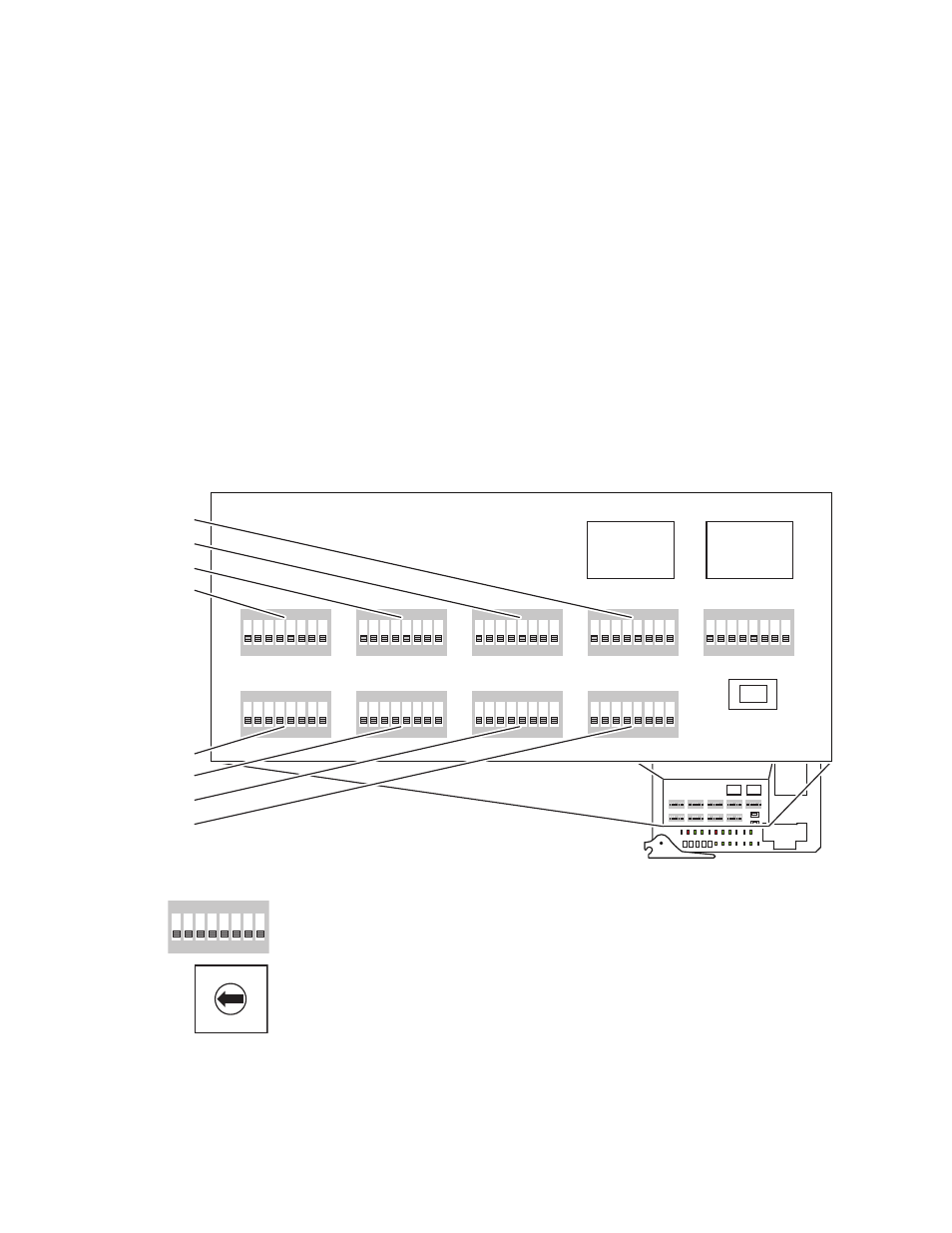
Crosspoint Bus Controller Settings
On the CRS-MC-C2 there are nine banks of DIP Switches (8 position with J
leads) and two Rotary Switches. See
.
4 5
6
7
8
9
A
B
C
D
E
F
0
1
2
3
1
8
7
6
5
4
3
2
ON
Figure 75. Crosspoint Bus Controller Switch Locations
Each bank has 8 DIP Switches with On and Off settings. The banks are
labeled with the DIP Switch position #
1
through #
8
and
ON
. There are only
two settings for each position, On or Off. The Rotary Switches have sixteen
positions #
0
through #
F
which are labeled on the face of the switch. The
Rotary Switches face toward the LEDs on the module.
Before you can configure the Rotary and DIP switches you need to deter-
mine the physical configuration of the Concerto Matrix. Refer to
Matrix Configurations on page 38
to identify supported module configura-
tions.
8138_03_76r0
1
8
7
6
5
4
3
2
ON
1
8
7
6
5
4
3
2
ON
1
8
7
6
5
4
3
2
ON
1
8
7
6
5
4
3
2
ON
1
8
7
6
5
4
3
2
ON
1
8
7
6
5
4
3
2
ON
1
8
7
6
5
4
3
2
ON
1
8
7
6
5
4
3
2
ON
1
8
7
6
5
4
3
2
ON
PWR
OK
DONE
ACT
GND
+5V
ERROR
TC2
PRE
S
BUSY
48K
PRES
LINK
SYNC
ERR
RECV
VI 2
PRES
XMIT
VI 1
PRES
CLEAR MEM
RESET
TX
RX
FAST
COL
TC1
PRES
+2.5V
+3.3V
A_LEVEL
B_LEVEL
A_OPTION
S
C_LEVEL
D_LEVEL
B_OPTION
S
C_OPTION
S
D_OPTION
S
MODE/IN
S
EL
S
11
S
12
S
13
A
B
C
D
E
F
G
H
A
B
C
D
E
F
G
H
A
B
C
D
E
F
G
H
A
B
C
D
E
F
G
H
M A T R I X MAP
C O N F I G
1
8
7
6
5
4
3
2
ON
1
8
7
6
5
4
3
2
ON
1
8
7
6
5
4
3
2
ON
1
8
7
6
5
4
3
2
ON
1
8
7
6
5
4
3
2
ON
1
8
7
6
5
4
3
2
ON
1
8
7
6
5
4
3
2
ON
1
8
7
6
5
4
3
2
ON
1
8
7
6
5
4
3
2
ON
CLEAR MEM
A_LEVEL
B_LEVEL
A_OPTION
S
C_LEVEL
D_LEVEL
B_OPTION
S
C_OPTION
S
D_OPTION
S
MODE/IN
S
EL
S
11
S
12
S
13
A
B
C
D
E
F
G
H
A
B
C
D
E
F
G
H
A
B
C
D
E
F
G
H
A
B
C
D
E
F
G
H
M A T R I X MAP
C O N F I G
DIP Switches
S10 (D_OPTIONS)
S9 (D_LEVEL)
S8 (C_OPTIONS)
S7 (C_LEVEL)
DIP Switches
S2 (A_LEVEL)
S3 (A_OPTIONS)
S4 (B_LEVEL)
S5 (B_OPTIONS)
Rotary
Switch
Rotary
Switch