Grass Valley Concerto Routing Matrix v.1.8.1 User Manual
Page 94
94
Concerto — Installation and Service Manual
Section 2 — Installation
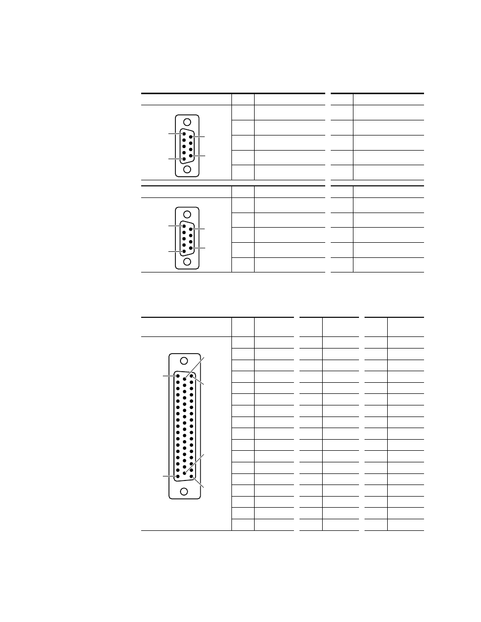
contains pinout information for the 9 Pin D connectors on the Port
9 Pin D Backplanes.
contains pinout information for the Input and Output connectors
on the Balanced 50 Pin D Analog Audio Backplane.
Table 40. Matrix Port Backplane D Connector Pinouts
Controlled
Pin
Function
Pin
Function
1
GND
6
GND
2
TX-
7
TX+
3
RX+
8
RX-
4
GND
9
GND-
5
Not Used
-
-
Controlling
Pin
Function
Pin
Function
1
GND
6
GND
2
RX-
7
RX+
3
TX+
8
TX-
4
GND
9
GND
5
Not Used
-
-
Table 41. Analog Audio Input/Output 50 Pin D Connector Pinouts
Input/Output D Connector
Analog Audio
Pin
Function
Pin
Function
Pin
Function
1
Ground
18
1A-
34
1A+
2
1B+
19
1B-
35
Ground
3
Ground
20
2A-
36
2A+
4
2B+
21
2B-
37
Ground
5
Ground
22
3A-
38
3A+
6
3B+
23
3B-
39
Ground
7
Ground
24
4A-
40
4A+
8
4B+
25
4B-
41
Ground
9
Ground
26
5A-
42
5A+
10
5B+
27
5B-
43
Ground
11
Ground
28
6A-
44
6A+
12
6B+
29
6B-
45
Ground
13
Ground
30
7A-
46
7A+
14
7B+
31
7B-
47
Ground
15
Ground
32
8A-
48
8A+
16
8B+
33
8B-
49
Ground
17
-
-
-
50
-
5
6
9
1
9 Pin D Female
5
6
9
1
9 Pin D Female
50 Pin D Female
1
17
33
50
18
34