Module identification, Figure 3 – Grass Valley Concerto Routing Matrix v.1.8.1 User Manual
Page 35
Concerto — Installation and Service Manual
35
Module Identification
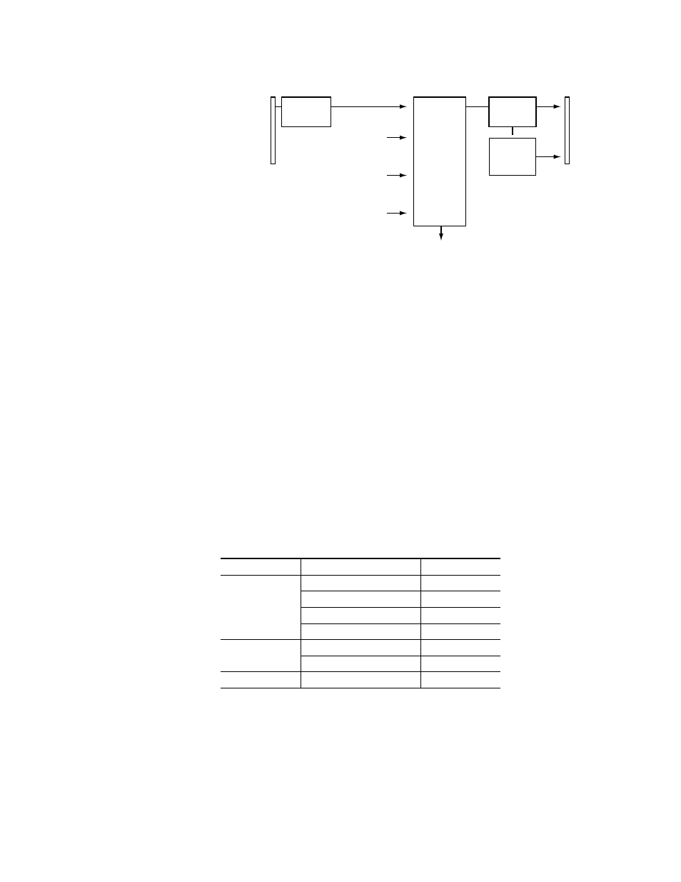
Figure 3. Block Diagram for Module in Slot 1 in Analog Audio Mono 256x256 Matrix
Module Identification
The modules Crosspoint configuration can be 128x32, 64x32, or 32x32. The
64x32 Crosspoint configuration will allow two modules to create a 64x64
matrix but will not allow larger matrices. The 64x32 Crosspoint modules
can only be used in slots 1 (top) and 2 or slots 3 and 4 of the 7 RU Concerto
or 8 RU Concerto+ frames to create 64x64 matrices. The 32x32 Crosspoint
configuration modules cannot be combined into larger matrices but can be
used in all of the Concerto frames. The Analog audio matrices also have
three Maximum Input Level specifications +24 dBu, +18 dBu, and +15 dBu.
The attributes of each module are identified by the last two digits of the
part number.
identifies Analog video modules.
Table 3. Analog Video Modules 671-6369-##
## Range
Matrix Size
Modules
00-49
128x128
4
96x96
3
64x64
2
32x32
1
50-79
64x64
a
a
If a 7 RU Concerto or 8 RU Concerto+ frame is used to create this matrix the modules
must be placed in slots 1 and 2 or slots 3 and 4
2
32x32
1
80-99
32x32
1
64 Inputs
(1A/1B to
32A/32B)
from Slot 1
backplane
Input (1A/1B to
32A/32B) Distribution
to Slots 2, 3, & 4
64 Inputs
(33A/33B to 64A/64B)
from Matrix 2
64 Inputs
(97A/97B to 128A/128B)
from Matrix 4
64 Inputs
(65A/65B to 96A/96B)
from Matrix 3
64 Outputs
(1A/1B to
32A/32B)
to Slot 1
backplane
Time
Division
Multiplexing
256x64
64x1
Monitor
Crosspoint
A to D
Converter
D to A
Converter
8138_00_63r0