Jupiter controlled non-redundant systems, Encore controlled redundant systems, Inspect the new controller module – Grass Valley Concerto Routing Matrix v.1.8.1 User Manual
Page 148: Remove the old controller module, Insert and seat the new controller module. the, Power ok) and, Led to turn on. continued commands prompt the, Led to flash, Inspect the new controller modules, Set the dip switch bank s11 switch number 1 to
148
Concerto — Installation and Service Manual
Section 5 — Maintenance and Troubleshooting
Jupiter Controlled Non-Redundant Systems
1.
Inspect the new Controller module.
2.
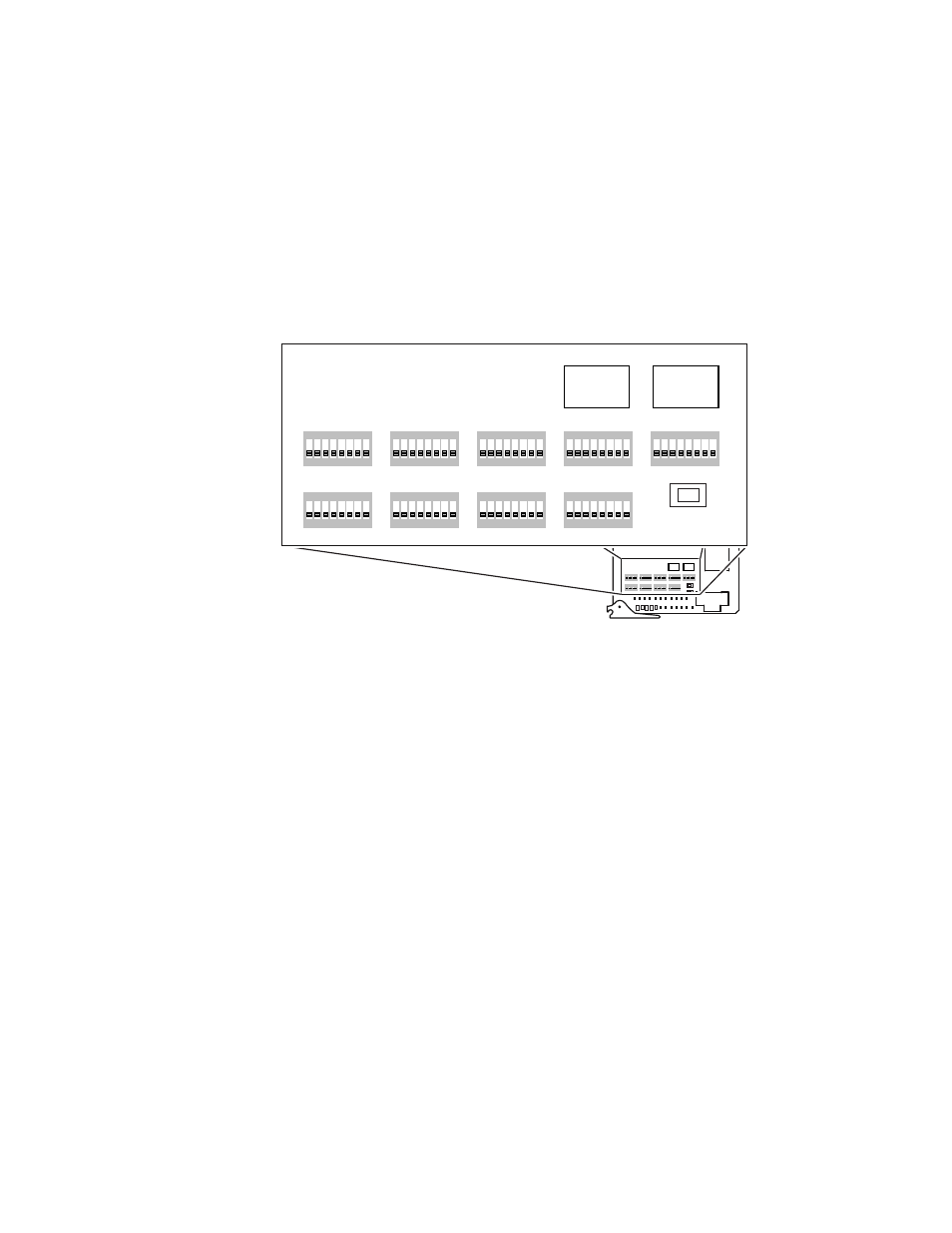
Set each of the 9 DIP switch settings and two rotary switch settings to
match that of the currently installed Controller.
These can be viewed on the currently used module while it is active in
the Concerto chassis. Note the status of the LEDs on the front edge of
the module.
Figure 83. DIP Switches and Rotary Switches
3.
Remove the old Controller module.
4.
Insert and seat the new Controller module.
The
PWR OK
(power OK) and
DONE
LED will light signifying the module
is up and ready to receive commands. The next command sent from the
control system will cause the
ACT
(active) LED to turn on.
The next command sent from the control system will prompt the
ACT
LED to turn on. Continued commands prompt the
ACT
LED to flash.
5.
Send a switch command from the control system and verify that the
switch was executed.
Encore Controlled Redundant Systems
1.
Inspect the new Controller modules.
2.
Set the DIP Switch bank S11 switch number 1 to
ON
. Switches 2 to 8 are
set to
OFF
.
3.
Remove one old Controller module.
0732_00_1r0
1
8
7
6
5
4
3
2
ON
1
8
7
6
5
4
3
2
ON
1
8
7
6
5
4
3
2
ON
1
8
7
6
5
4
3
2
ON
1
8
7
6
5
4
3
2
ON
1
8
7
6
5
4
3
2
ON
1
8
7
6
5
4
3
2
ON
1
8
7
6
5
4
3
2
ON
1
8
7
6
5
4
3
2
ON
PWR
OK
DONE
ACT
GND
+5V
ERROR
TC2
PRES
BUSY
48K
PRES
LINK
SYNC
ERR
RECV
VI 2
PRES
XMIT
VI 1
PRES
CLEAR MEM
RESET
TX
RX
FAST
COL
TC1
PRES
+2.5V
+3.3V
A_LEVEL
B_LEVEL
A_OPTIONS
C_LEVEL
D_LEVEL
B_OPTIONS
C_OPTIONS
D_OPTIONS
MODE/IN
SEL
S11
S12
S13
A
B
C
D
E
F
G
H
A
B
C
D
E
F
G
H
A
B
C
D
E
F
G
H
A
B
C
D
E
F
G
H
M A T R I X MAP
C O N F I G
1
8
7
6
5
4
3
2
ON
1
8
7
6
5
4
3
2
ON
1
8
7
6
5
4
3
2
ON
1
8
7
6
5
4
3
2
ON
1
8
7
6
5
4
3
2
ON
1
8
7
6
5
4
3
2
ON
1
8
7
6
5
4
3
2
ON
1
8
7
6
5
4
3
2
ON
1
8
7
6
5
4
3
2
ON
CLEAR MEM
A_LEVEL
B_LEVEL
A_OPTIONS
C_LEVEL
D_LEVEL
B_OPTIONS
C_OPTIONS
D_OPTIONS
MODE/IN
SEL
S11
S12
S13
A
B
C
D
E
F
G
H
A
B
C
D
E
F
G
H
A
B
C
D
E
F
G
H
A
B
C
D
E
F
G
H
M A T R I X MAP
C O N F I G
Rotary
Switch
Rotary
Switch