Network requirements – H3C Technologies H3C S5830V2 Series Switches User Manual
Page 191

180
FC and FCoE configuration example by using FC
interfaces and VFC interfaces (in standalone mode)
Network requirements
As shown in
:
•
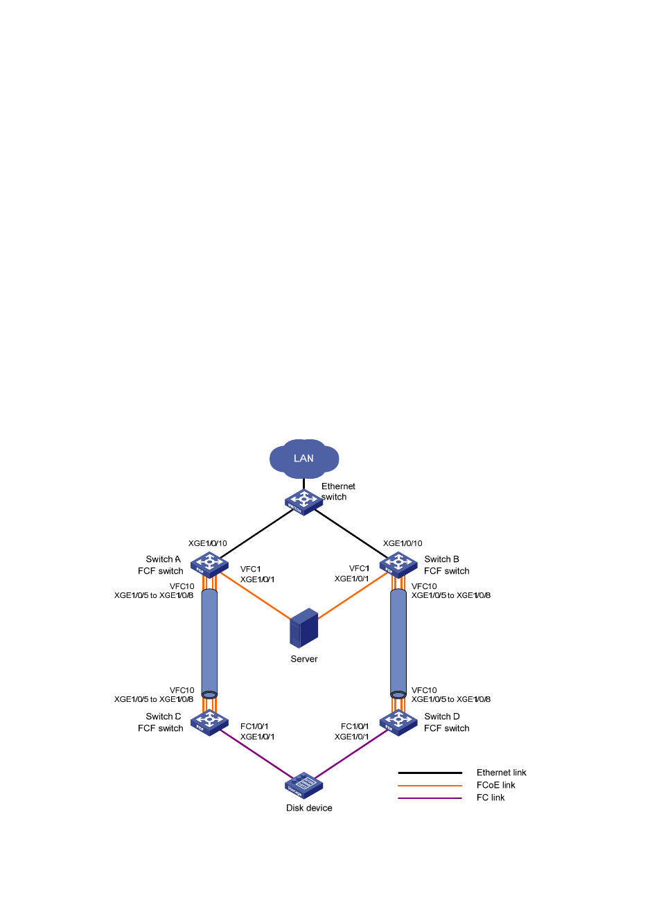
Switch A and Switch B are connected to an Ethernet switch, and operate at the access layer of the
LAN.
•
Switch A and Switch B are connected to Switch C and Switch D, respectively.
•
The four switches operate as the FCF switches of the SANs.
Configure FC and FCoE to meet the following requirements:
•
The transmission network formed by Switch A, Switch B, and the Ethernet switch can use the server
to provide services for the LAN. The transmission network formed by switches A through D can
enable the server to access the disk device.
•
Link backup is used to implement high availability for the packets to and from the server and disk
device.
•
The bandwidth is increased for the link between Switch A and Switch C and the link between Switch
B and Switch D, and link backup and load sharing are implemented.
Figure 46 Network diagram
L
ink aggr
egation 2
L
ink aggr
egation 1
- H3C S12500X-AF Series Switches (3 pages)
- H3C S12500X-AF Series Switches (3 pages)
- H3C S12500X-AF Series Switches (53 pages)
- H3C S12500 Series Switches (19 pages)
- H3C MSV 50 (8 pages)
- H3C S12500 Series Switches (21 pages)
- H3C S9500E Series Switches (4 pages)
- H3C S7500E Series Switches (3 pages)
- H3C WA2200 Series WLAN Access Points (42 pages)
- H3C S12500-X Series Switches (8 pages)
- H3C SR6600 (64 pages)
- H3C S9500E Series Switches (36 pages)
- H3C WA3600 Series Access Points (237 pages)
- H3C S9500E Series Switches (270 pages)
- H3C MSR 900 (249 pages)
- H3C S12500 Series Switches (163 pages)
- H3C S12500 Series Switches (170 pages)
- H3C MSR 900 (96 pages)
- H3C MSR 900 (443 pages)
- H3C MSR 900 (468 pages)
- H3C S9500E Series Switches (32 pages)
- H3C S9500E Series Switches (241 pages)
- H3C S12500 Series Switches (39 pages)
- H3C S6800 Series Switches (59 pages)
- H3C LSBM1WCM2A0 Access Controller Module (197 pages)
- H3C S10500 Series Switches (27 pages)
- H3C LSBM1WCM2A0 Access Controller Module (226 pages)
- H3C S6300 Series Switches (188 pages)
- H3C MSR 900 (410 pages)
- H3C MSR 900 (239 pages)
- H3C WA3600 Series Access Points (394 pages)
- H3C S10500 Series Switches (2 pages)
- H3C S10500 Series Switches (2 pages)
- H3C S10500 Series Switches (2 pages)
- H3C S10500 Series Switches (2 pages)
- H3C S10500 Series Switches (2 pages)
- H3C S10500 Series Switches (2 pages)
- H3C S10500 Series Switches (2 pages)
- H3C S10500 Series Switches (1 page)
- H3C S7500E Series Switches (19 pages)
- H3C S7500E Series Switches (115 pages)
- H3C S6300 Series Switches (58 pages)
- H3C S6300 Series Switches (208 pages)
- H3C S6300 Series Switches (251 pages)
- H3C S10500 Series Switches (140 pages)
