Advertising optimal routes in the ip routing table, Bgp path selection configuration example – H3C Technologies H3C S12500-X Series Switches User Manual
Page 281

267
State : valid, internal-confed, best,
The output indicates the following:
•
Switch F can send route information to Switch B and Switch C through the confederation by
establishing only an EBGP connection with Switch A.
•
Switch B and Switch D are in the same confederation, but belong to different sub-ASs. They obtain
external route information from Switch A and generate identical BGP route entries although they
have no direct connection in between.
346B
BGP path selection configuration example
627B
Network requirements
In
1165H
Figure 66
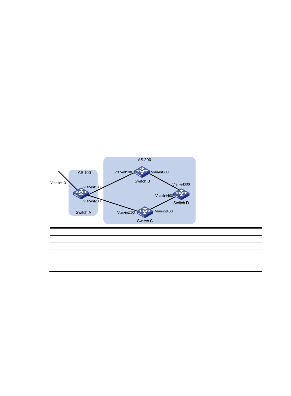
, all switches run BGP. EBGP runs between Switch A and Switch B, and between Switch A
and Switch C. IBGP runs between Switch B and Switch D, and between Switch D and Switch C. OSPF is
the IGP protocol in AS 200.
Configure routing policies, making Switch D use the route 1.0.0.0/8 from Switch C as the optimal.
Figure 66 Network diagram
Device Interface
IP
address
Device
Interface IP
address
Switch A
Vlan-int101
1.0.0.1/8
Switch D
Vlan-int400
195.1.1.1/24
Vlan-int100
192.1.1.1/24
Vlan-int300 194.1.1.1/24
Vlan-int200
193.1.1.1/24
Switch C
Vlan-int400 195.1.1.2/24
Switch B
Vlan-int100
192.1.1.2/24
Vlan-int200
193.1.1.2/24
Vlan-int300
194.1.1.2/24
628B
Configuration procedure
1.
Configure IP addresses for interfaces. (Details not shown.)
2.
Configure OSPF on Switch B, Switch C, and Switch D:
# Configure Switch B.
[SwitchB] ospf
[SwitchB-ospf] area 0
[SwitchB-ospf-1-area-0.0.0.0] network 192.1.1.0 0.0.0.255
[SwitchB-ospf-1-area-0.0.0.0] network 194.1.1.0 0.0.0.255
[SwitchB-ospf-1-area-0.0.0.0] quit
[SwitchB-ospf-1] quit
