1 redundant plate installation, 4 1:1 redundant plate installation – Comtech EF Data HPCST-5000 User Manual
Page 100
Redundant System Installation
High-Power C-Band Satellite Terminal
4–18
Rev. 0
4.3.4
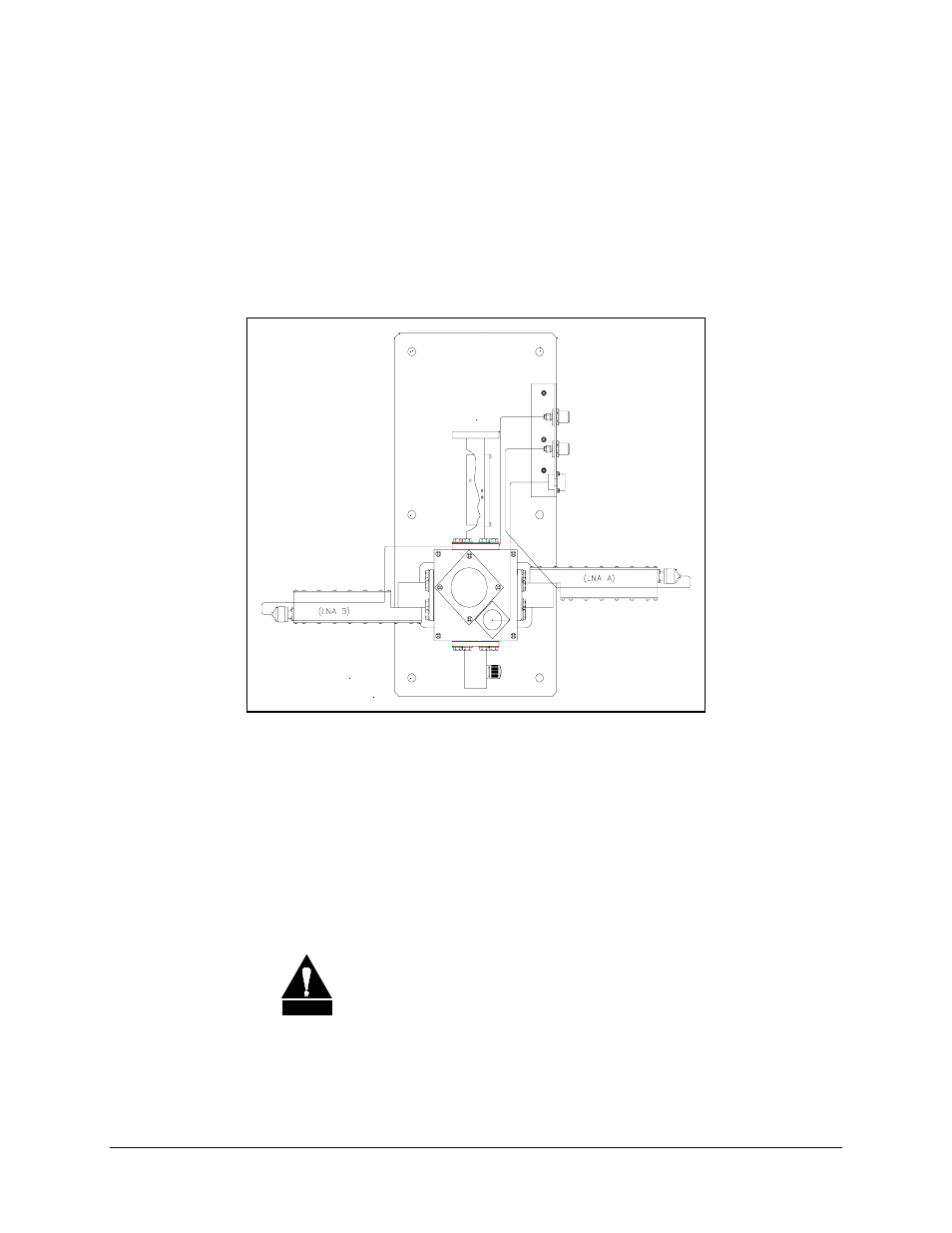
1:1 Redundant Plate Installation
Note: Refer to Section 8, Figure 8-2 for cabling configuration.
The 1:1 redundant plate is shown in Figure 4-2 as follows:
Figure 4-2. 1:1 Redundant Plate
Install the 1:1 redundant plate as follows:
1. Mount the 1:1 redundant plate to the antenna.
Note: The type of mounting is determined by the brand of antenna on which the
equipment will be installed.
2. Remove the plastic cover from the RF IN connector of the redundant plate.
CAUTION
After removing the protective cover, ensure that no foreign material
or moisture enters the 1:1 redundant plate’s waveguide.
See also other documents in the category Comtech EF Data Equipment:
- CDD-880 (124 pages)
- CDM-800 (130 pages)
- ODMR-840 (184 pages)
- CDM-750 (302 pages)
- CDM-840 (244 pages)
- SLM-5650A (420 pages)
- CTOG-250 (236 pages)
- CDM-700 (256 pages)
- CDM-760 (416 pages)
- CDM-710G (246 pages)
- CDM-600/600L (278 pages)
- CDMR-570L (512 pages)
- CDM-625 (684 pages)
- CDM-625A (756 pages)
- CDD-564A (240 pages)
- CDD-564L (254 pages)
- CLO-10 (134 pages)
- MCED-100 (96 pages)
- CDMR-570AL (618 pages)
- CDM-600 LDPC (2 pages)
- BUC Power Supply Ground Cable (2 pages)
- MPP70 Hardware Kit for CDM-570L (4 pages)
- MPP50 Hardware Kit for CDM-570L (4 pages)
- CDM-625 DC-AC Conversion (4 pages)
- CDM-625 DC-AC Conversion with IP Packet Processor (4 pages)
- DMDVR20 LBST Rev 1.1 (117 pages)
- DMD2050E (212 pages)
- DMD-2050 (342 pages)
- DMD1050 (188 pages)
- OM20 (220 pages)
- QAM256 (87 pages)
- DD240XR Rev Е (121 pages)
- MM200 ASI Field (5 pages)
- DM240-DVB (196 pages)
- MM200 (192 pages)
- CRS-150 (78 pages)
- CRS-280L (64 pages)
- CRS-170A (172 pages)
- CRS-180 (136 pages)
- SMS-301 (124 pages)
- CiM-25/8000 (186 pages)
- CiM-25 (26 pages)
- CRS-500 (218 pages)
- CRS-311 (196 pages)
- CIC-20 LVDS to HSSI (26 pages)